Chaotic Circuit Simulation using LTspice

Thread Starter

akshaj202

Joined Jul 29, 2021
9
I'm trying to simulate a chaotic circuit involving a single equilibrium point, but when I try simulating the circuit I'm getting an error with one of the multiplier blocks (AD633) regarding the time step being too small. I need my simulation to run for around 100-200 sec for getting the desired results.

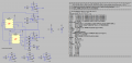
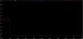
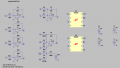
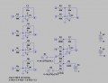
The circuit I want to simulate is in the figure 1.PNG and the corresponding LTspice model in 2.PNG and on simulating I'm getting an error as shown in 3.PNG

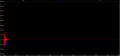
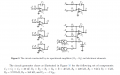
So, instead of using the AD633 analog multiplier I used a behavioural voltage source for the product of the 2 signals and the LTspice model of the same is shown in 4.PNG. But by doing so this resulted in a very bad output, instead of getting chaotic phenomenon, the outputs x,y,z saturated to the Op-Amps Vsat.

Is there anything wrong in my model and is there anyway I can get it right?
 

Attachments

Yffig

Joined Aug 25, 2019
29
(Mathematical) Chaos functions are generated from non linear differential equations. When an EE student (45 year ago...), I was trained to using Analog Circuitry Computers for that purpose. Are you able to write down the equation the circuit is supposed to solve ?
 

Thread Starter

akshaj202

Joined Jul 29, 2021
9
(Mathematical) Chaos functions are generated from non linear differential equations. When an EE student (45 year ago...), I was trained to using Analog Circuitry Computers for that purpose. Are you able to write down the equation the circuit is supposed to solve ?
Yes, the non-linear 3 dimensional differential equation that I'm trying to simulate are -
x' = z
y' = - x - z
z' = 0.1x + 5y - z + xy - 0.3xz + 1
where all the derivatives are wrt time
 

Yffig

Joined Aug 25, 2019
29
Yes, the non-linear 3 dimensional differential equation that I'm trying to simulate are -
x' = z
y' = - x - z
z' = 0.1x + 5y - z + xy - 0.3xz + 1
where all the derivatives are wrt time
Fine ! (I didn't check if they are the actual equations...). Enter these equations into a Math Graph software as the free https://www.desmos.com (refer to https://learn.desmos.com/derivatives) and you'll get the simulation to understand the behaviour of the circuit.
Have a nice day.
[EDIT]:
OOPS... I was mistaken... Desmos does not solve diff. equations and the few free differential equations solvers i know only work with linear equations.
 
Last edited:

Thread Starter

akshaj202

Joined Jul 29, 2021
9
Fine ! (I didn't check if they are the actual equations...). Enter these equations into a Math Graph software as the free https://www.desmos.com (refer to https://learn.desmos.com/derivatives) and you'll get the simulation to understand the behaviour of the circuit.
Have a nice day.
[EDIT]:
OOPS... I was mistaken... Desmos does not solve diff. equations and the few free differential equations solvers i know only work with linear equations.
But I needed to simulate the circuit shown, not the differential equations. I've already simulated and understood the behaviour of the dynamical equations using SIMULINK MATLAB. I wanted to observe the same by building the circuit
 

Yffig

Joined Aug 25, 2019
29
But I needed to simulate the circuit shown, not the differential equations. I've already simulated and understood the behaviour of the dynamical equations using SIMULINK MATLAB. I wanted to observe the same by building the circuit
OK ! with a MatLab simulation you know what are the solutions for x, y & z, have checked that they fit within the voltage range of the circuit and that the accurate initial conditions provide a chaotic behaviour of the circuit to be simulated.
Would you be kind enough to post the two .asc files you have tested ?
Thx
 

Alec_t

Joined Sep 17, 2013
14,280
I don't think the integrators U1-3 are doing what you expect, but I can't see any obvious reason. I ran a sim with those integrators replaced by behavioural voltage sources and got quite different results from your sims.
Chaos2.jpg
 

Attachments

Yffig

Joined Aug 25, 2019
29
I ran the behavorial circuit you posted after having added the scale factor *0.1 on the multipliers. (attached Chaotic_Yffig.png). Does the very beggining looks like the plots you had with SimuLink ?
The voltage saturates at 15V just before 30 ms so I changed the power supplies to +/-150V...same problem just before 44 ms. (attached Chaotic_Yffig at 150V.png).
The circuit is very sensitive to the initial conditions. Where did you get those 3 values from ?
To check the behaviour of the integrators, I made a simulation for a simple 2nd order linear diff eq. (d²y/dt²+y = 0, y(0)=1V): the integrators run perfectly with the Universal Op Amp you choose and also with a standard LT1057A. The amplitude is limited by the supply voltages (and actually this non linearity is an advantage to stabilize the amplitudes).(.asc file is attached)
Regarding Alec_t answer, if you run its .asc file for 150 s or more, the simulation also fails.
Linear_2nd_Order_Yffig.png
Chaotic_Yffig.pngChaotic_Yffig at 150V.png
 

Attachments

Last edited:

Yffig

Joined Aug 25, 2019
29
Hi !
The site given by AlbertHall (thanks for the link !) has a very interesting page : https://www.chaotic-circuits.com/10-creating-lorenz-butterfly/
where you can download the asc. file for simulating Lorentz's butterfly using AD633 Multipliers & LT1057 Op amps and run it directly.
I ran it for 1000s without any issue. Attached is the phase diagram i obtained (10s sim. time).
It could be a good starting example for you to implement your equations.
Have a nice day !

Lorentz_Butterfly (Yffig).png
 

Thread Starter

akshaj202

Joined Jul 29, 2021
9
I don't think the integrators U1-3 are doing what you expect, but I can't see any obvious reason. I ran a sim with those integrators replaced by behavioural voltage sources and got quite different results from
Hi !
The site given by AlbertHall (thanks for the link !) has a very interesting page : https://www.chaotic-circuits.com/10-creating-lorenz-butterfly/
where you can download the asc. file for simulating Lorentz's butterfly using AD633 Multipliers & LT1057 Op amps and run it directly.
I ran it for 1000s without any issue. Attached is the phase diagram i obtained (10s sim. time).
It could be a good starting example for you to implement your equations.
Have a nice day !

View attachment 244959
Thanks a lot for this, but I'm not able to download the .asc file. It would be kind of you if you could attach the same here
 

Thread Starter

akshaj202

Joined Jul 29, 2021
9
Hi !
The site given by AlbertHall (thanks for the link !) has a very interesting page : https://www.chaotic-circuits.com/10-creating-lorenz-butterfly/
where you can download the asc. file for simulating Lorentz's butterfly using AD633 Multipliers & LT1057 Op amps and run it directly.
I ran it for 1000s without any issue. Attached is the phase diagram i obtained (10s sim. time).
It could be a good starting example for you to implement your equations.
Have a nice day !

View attachment 244959
I've done the simulation as you suggested and now I'm able to run the simulation for as long as I want. The results are perfectly fine when there are no initial conditions set (that is all the voltages start from zero), the system stabilizes to the stable equilibrium point (0,50mV,0). But the problem here is that for observing the hidden chaotic attractor I need to set the initial conditions and when I do so the results aren't satisfactory. The results for no initial conditions and with the initial conditions is shown in the figures below (For the initial conditions case the opamps output seems to saturate). Is there anything wrong with the inital conditions or is it still a problem with the ltspice model? I've attached the pdf of the circuit and its analysis which I'm trying to simulate. Also attached the .asc file of the new model
 

Attachments

Yffig

Joined Aug 25, 2019
29
I'm sorry but have a look at the attached two simulations side by side, they are the same and new_trial file doesn't correspond to the n1.png you posted.
My_Lorenz versus New_trial.png
 

Thread Starter

akshaj202

Joined Jul 29, 2021
9
After what time? They don't when I run the sim for 10s.
Did you remember to check 'Skip initial operating point solution'? (It's not checked in your post #14 asc file).
I meant when I set the ic to some values then the opamp saturates. But when I don't set any ic then it seems to work fine
 
Top