Facebook
 Google
 GitHub
 Linkedin

MisterBill2
- Joined Jan 23, 2018
- 28,509
I like the circuit shown in post #16, except that an actual voltage regulator instead of a shunt zener diode will be a better choice. An actual regulator will be more stable and use less power. But do not leave out the 0.1 mfd bypass capacitors for the regulator.
But the gage indication may only be correct at one point if either or both of the temperature sensors are not linear. But most OEM gages are not actually calibrated other than "Hot" and "cold", so that may be close enough.
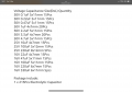
The capacitors of the correct value, as listed in the attachment, will work well.
But the gage indication may only be correct at one point if either or both of the temperature sensors are not linear. But most OEM gages are not actually calibrated other than "Hot" and "cold", so that may be close enough.
The capacitors of the correct value, as listed in the attachment, will work well.
Last edited: