 Facebook
 Google
 GitHub
 Linkedin
I had to transform a 10Vpp (without DC level) signal into a 5Vpp with a virtual ground at 2.5V DC. I've come with this simple circuit that works both in simulation and real life. But I would like to know if there is something that I've missed in this design:

The op amp is configured as non-inverted with gain. R8 appears disconnected in the capture, but it is connected to the negative input.
Related with this:
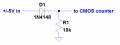
What happens if I insert a 10Vpp (±5V) to an op amp connected to 5V and ground (as power source) using an AC coupling capacitor? Will the negative part of the signal damage the amplifier?
The op amp is configured as non-inverted with gain. R8 appears disconnected in the capture, but it is connected to the negative input.
Related with this:
What happens if I insert a 10Vpp (±5V) to an op amp connected to 5V and ground (as power source) using an AC coupling capacitor? Will the negative part of the signal damage the amplifier?
Last edited:
")


