Center tap microwave transformer.

Thread Starter

Hutch2793

Joined Jul 7, 2020
133
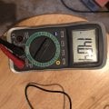
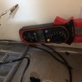
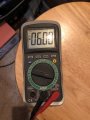
I have rewound secondary microwave transformer with a center tap that is at 7.2 volts and the total voltage from the entire Winding at 14.2. When I hook it to the full rectifier it gives me 12.45 volts dc. Shouldn’t it be half the voltage? So right around 7? What am I missing?
 

dl324

Joined Mar 30, 2015
16,839
When I hook it to the full rectifier it gives me 12.45 volts dc. Shouldn’t it be half the voltage? So right around 7? What am I missing?
It would be helpful if you showed a schematic for how you have the rectifier connected. It isn't clear to me if you were using the center tap (or which side) or the full winding or if you have a filter cap. If you're using a DVM, it won't measure pulsating DC accurately.

When volts (or V) isn't qualified, it's assumed to be VDC. AC voltages are assumed to be RMS unless specified otherwise.

Since you're getting 14.2VAC for the whole secondary, the windings on either side of the tap aren't the same number of turns.
7.2VAC = 10.18V (peak) - 0.7V (diode) = 9.48V
7.0VAC = 9.9V - 0.7V = 9.2V
14.2VAC = 20.07V - 0.7V = 19.38V

Your reading doesn't make sense.
 

Thread Starter

Hutch2793

Joined Jul 7, 2020
133
14.04-entire secondary
7.04- center tap
AC^^^^^^^^^^

6 volts dc when connected to fulll wave rectifier. (I’m not a professional, obviously! I’m just experimenting, so none of what yoU see is permanent and I know the way it is now it extremely dangerous.) I will be taking it apart immediately after posting this.
 

Attachments

vu2nan

Joined Sep 11, 2014
345
It appears that you have connected the bridge rectifier on the 7.2V side of the centre tap.

untitled5.JPG

With a bridge rectifier, without a filter capacitor the DC voltage would be AC voltage minus the voltage drop across 2 diodes.

Vdc = 7.2 - (2 x 0.6) = 6 V.
 
Last edited:

dl324

Joined Mar 30, 2015
16,839
With a bridge rectifier, without a filter capacitor the DC voltage would be AC voltage minus the voltage drop across 2 diodes.

Vdc = 7.2 - (2 x 0.6) = 6 V.
He never said he was using a bridge rectifier.

The secondary voltage is VAC RMS. You need to multiply by the square root of 2 to get peak DC. Without a filter cap, the output is pulsating DC which can't be measured with a DVM.

The OP needs to post a schematic so we know what he's talking about because the description provided isn't sufficient.
 

Thread Starter

Hutch2793

Joined Jul 7, 2020
133
He never said he was using a bridge rectifier.

The secondary voltage is VAC RMS. You need to multiply by the square root of 2 to get peak DC. Without a filter cap, the output is pulsating DC which can't be measured with a DVM.

The OP needs to post a schematic so we know what he's talking about because the description provided isn't sufficient.
I’m not experience, so chances are the schematic will be wrong and you will give me the wrong solution. Was the picture not enough? Here’s a hand drawn jewel of a schematic. It is probably wrong, but it’s the best of my ability and knowledge at the moment.
 

Thread Starter

Hutch2793

Joined Jul 7, 2020
133
I used a 50 amp Rectifier because of the initial voltage rush when turning power on/off. My transformer settles around 4.20 amps no load.
 

dl324

Joined Mar 30, 2015
16,839
I’m not experience, so chances are the schematic will be wrong and you will give me the wrong solution.
This is a serious problem because your descriptions aren't very detailed.

You said you were using a full wave rectifier. This is what I think of when I read that:
clipimage.jpg

What you drew is called a bridge rectifier or full wave bridge rectifier:
clipimage.jpg
Was the picture not enough?
Pictures should be a last resort. They're most useful when you doubt your ability to wire things correctly.

Schematics are always preferred. Words, pictures, and cartoons, not so much.

EDIT: rotated, cropped schematic:
clipimage.jpg
You've drawn some of the diodes backwards.

Since you don't have a filter cap, the output from the rectifier is pulsating DC which can't be measured accurately by a DC voltmeter.
 
Last edited:

Thread Starter

Hutch2793

Joined Jul 7, 2020
133
This is a serious problem because your descriptions aren't very detailed.

You said you were using a full wave rectifier. This is what I think of when I read that:
View attachment 212924

What you drew is called a bridge rectifier or full wave bridge rectifier:
View attachment 212925
Pictures should be a last resort. They're most useful when you doubt your ability to wire things correctly.

Schematics are always preferred. Words, pictures, and cartoons, not so much.
I posted the component I bought. It was called a full wave rectifier online. I apologize, like I said I’m trying to learn. Is the online description of the component wrong? Would you like me to redraw it? I understand it doesn’t meet your expectations, but you have all the info you need. I will make sure to represent the schematic correctly next time. Maybe it is because this is online, but “not cartoons” sounds like your trying to be smart. Not everyone has your experience in the field.

Something about computers makes people pretend to be way more alpha then they ever will be in person. It’s completely unnecessary. If I’m wrong then I apologize for being so sensitive.

My drawing should have looked like the center picture. What is the math to calculate proper filter capacitor and resistor values?
 

dl324

Joined Mar 30, 2015
16,839
I posted the component I bought. It was called a full wave rectifier online.
It should always have bridge in the name. Bridge rectifier or, less commonly, full wave bridge rectifier (full wave is understood because you wouldn't use one as a half wave rectifier).
What is the math to calculate proper filter capacitor and resistor values?
It depends on the application. What is your intended output voltage and current?
I said I’m trying to learn.
That's fine, but you need to pay attention to details. Since you're learning, it's understandable that you wouldn't know how to describe things or ask questions properly, but you need to be able to accept constructive criticism. Electronics is fairly precise field; units and capitalization are significant.
 
Last edited:

vu2nan

Joined Sep 11, 2014
345
He never said he was using a bridge rectifier.

The secondary voltage is VAC RMS. You need to multiply by the square root of 2 to get peak DC. Without a filter cap, the output is pulsating DC which can't be measured with a DVM.

The OP needs to post a schematic so we know what he's talking about because the description provided isn't sufficient.
Hi Dennis,

The last photograph clearly shows a KBPC 5010, which is a bridge rectifier!

- Nandu.
 

Thread Starter

Hutch2793

Joined Jul 7, 2020
133
It should always have bridge in the name. Bridge rectifier or, less commonly, full wave bridge rectifier (full wave is understood because you wouldn't use one as a half wave rectifier).
It depends on the application. What is your intended output voltage and current?
That's fine, but you need to pay attention to details. Since you're learning, it's understandable that you wouldn't know how to describe things or ask questions properly, but you need to be able to accept constructive criticism. Electronics is fairly precise field; units and capitalization are significant.
Absolutely, I agree with constructive criticism being a necessity. Would you agree that the word “cartoons” in reference to my cartoonish schematic was a clever jab. I do the same things at work sometimes and I have to try not to, because it shows weakness In my self worth. I can honestly say when I make remarks like that it come from a place of feeling less than.

It seemed a step past constructive criticism, being that this is a forum for the knowledgeable to help those who are not. Someone who goes out their way to help, but does it in a way as to let the person know they are not as smart makes the knowledgeable look, well less than.

Obviously you didn’t explode on me, or flat out deny it, so the above does not apply to you. Thank you for keeping it civilized and having a respectful exchange. Others don’t do those things and I think that is partly why their is so much division these days.
 

Thread Starter

Hutch2793

Joined Jul 7, 2020
133
The intended output is 14 Vac total on the secondary with the center tap being 7. It is right where I want it. The dc output is supposed to be 6-6.5.
 

Thread Starter

Hutch2793

Joined Jul 7, 2020
133
I work full time and go to school, so there will be a lot of errors in my posts because I have to sneak away to get enough time just to respond on this forum.
 
Top