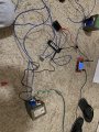
Center tap microwave transformer.

Thread Starter

Hutch2793

Joined Jul 7, 2020
133
What is the voltage regulation requirement? Is pulsating current okay?
The scope showed you a lot of information that isn't useful, e.g. RMS, peak to peak, and average voltage, and cycle, PW, and duty. You can measure or calculate the important things.

Don't get lulled in to using bogus information presented to 3 decimal places.

Clipped image:
View attachment 214117
Voltage requirement is 7 volts. I believe pulsing current is ok, but I wouldn’t mind smoothing it to learn how it’s done. For the testing I’m doing Pulsing current is ok.
 

dl324

Joined Mar 30, 2015
16,935
Voltage requirement is 7 volts. I believe pulsing current is ok,
You could use a power zener diode to reduce the peak to 7V.
but I wouldn’t mind smoothing it to learn how it’s done.
You have enough head room to use a 7V regulator. An LM317 with an external power transistor would let you adjust the voltage. The datasheet will give an example with an external pass transistor.
 

Thread Starter

Hutch2793

Joined Jul 7, 2020
133
You could use a power zener diode to reduce the peak to 7V.
I would use a capacitor to smooth and then a zener diode? What is the numbers on that. I had a peak of 11-12 volts I believe, so how much does the voltage drop from a zener?

“You have enough head room to use a 7V regulator. An LM317 with an external power transistor would let you adjust the voltage. The datasheet will give an example with an external pass transistor.”

I actually have lm317’s could I use a transistor and a potentiometer for variable voltage? how do you figure out the transistors needed?
sorry for all the questions, but I haven’t had any actual schooling on electrical engineering. I’m in calculus and physics now.
 

dl324

Joined Mar 30, 2015
16,935
I actually have lm317’s could I use a transistor and a potentiometer for variable voltage? how do you figure out the transistors needed?
You can use a variation of this circuit:
clipimage.jpg

The voltage is determined by R4 and R5.
\( V_{out} = 1.25V(1+\frac{R5}{R4}) \)

You need a power transistor that can handle the current and power dissipation.

LM195 is an integrated power transistor. You can't do that (parallel them without ballast resistors) with regular power transistors.

You can replace the NPN power transistors with a power PNP:
clipimage.jpg

If you want to control the current ratio in the regulator and pass transistor, you can do this:
(National Semiconductor Voltage Regulator Handbook)
clipimage.jpg

If you put the regulator and transistor on the same heatsink, the regulator can protect the power transistor.
 

Thread Starter

Hutch2793

Joined Jul 7, 2020
133
You can use a variation of this circuit:
View attachment 214127

The voltage is determined by R4 and R5.
\( V_{out} = 1.25V(1+\frac{R5}{R4}) \)

You need a power transistor that can handle the current and power dissipation.

LM195 is an integrated power transistor. You can't do that (parallel them without ballast resistors) with regular power transistors.

You can replace the NPN power transistors with a power PNP:
View attachment 214131

If you want to control the current ratio in the regulator and pass transistor, you can do this:
(National Semiconductor Voltage Regulator Handbook)
View attachment 214133

If you put the regulator and transistor on the same heatsink, the regulator can protect the power transistor.
All of these components are 3 amp max though. My transformer runs over 3 amps and I need it too. 3 amps is the minimum.
 

dl324

Joined Mar 30, 2015
16,935
I was typing in the exact part numbers you listed on the circuit though.
Which one? I posted 3.

The first was using a device that seems to be hard to find (LM195/395). The second shows the classical PNP external pass transistor. If you want to use an NPN, you can use a variation of the first circuit. The third circuit shows how to specify a specific current sharing between the regulator and pass transistor.
 

Thread Starter

Hutch2793

Joined Jul 7, 2020
133
Which one? I posted 3.

The first was using a device that seems to be hard to find (LM195/395). The second shows the classical PNP external pass transistor. If you want to use an NPN, you can use a variation of the first circuit. The third circuit shows how to specify a specific current sharing between the regulator and pass transistor.
Actually I just realized I save the wrong schematic and bought parts for a regulator circuit from a past thread.
 

dl324

Joined Mar 30, 2015
16,935
I have looked for the parts you have listed and they are tough to find. Sorry, I have been pretty busy.
You don't need to use the transistors in the circuit diagrams. Just pick something appropriate for the current, voltage, and power dissipation.

For an NPN power transistor, 2N3055 is commonly used. It's PNP complement is MJ2955.

AFAIK, NPN power transistors still cost less than PNP, so the two transistor combination in the first circuit is used.

Which circuit are you planning to implement?
 

Thread Starter

Hutch2793

Joined Jul 7, 2020
133
You don't need to use the transistors in the circuit diagrams. Just pick something appropriate for the current, voltage, and power dissipation.

For an NPN power transistor, 2N3055 is commonly used. It's PNP complement is MJ2955.

AFAIK, NPN power transistors still cost less than PNP, so the two transistor combination in the first circuit is used.

Which circuit are you planning to implement?
Probably the 1st, or 2nd. It all comes down to what I already have and can get the easiest. The least complicated method as well.
 

dl324

Joined Mar 30, 2015
16,935
Probably the 1st, or 2nd. It all comes down to what I already have and can get the easiest. The least complicated method as well.
Personally, I'd go with the 3rd. It lets you specify the current ratio between the regulator and pass transistor. If you mount both on the same heat sink, the built in safe area protection in the regulator can protect the pass transistor.

To use an NPN transistor instead of PNP, you can use this circuit from a Nat Semi Voltage Regulator Handbook:
clipimage.jpg
 

Thread Starter

Hutch2793

Joined Jul 7, 2020
133
Personally, I'd go with the 3rd. It lets you specify the current ratio between the regulator and pass transistor. If you mount both on the same heat sink, the built in safe area protection in the regulator can protect the pass transistor.

To use an NPN transistor instead of PNP, you can use this circuit from a Nat Semi Voltage Regulator Handbook:
View attachment 214447
Alright, I will look into getting those components. They will b a little harder to track down and take time for me to understand it.
 

MisterBill2

Joined Jan 23, 2018
18,568
We are talking about many different things. I’m trying to keep it all straight, I apologize. You say that it can’t be measure without one and you say it can’t be measured with one? “You can't measure unfiltered pulsating DC with a voltmeter. With a filter cap, you don't know what the meter is measuring because the DC range can't measure quickly varying voltages.” How do I measure then? I need a 7 Vdc voltage regulator and a capacitor, correct? I know I need a fuse, but is there anything else I need?
Actally you can measure the unfiltered DC and usually you will get the peak voltage or close to it. But the number is not very useful. So add a capacitor of several microfarads across the voltage and you will read much closer to the peak voltage. That voltage will drop as you draw current with a load.
There is certainly a big difference between making a measurement and making an ACCURATE measurement.
 

dl324

Joined Mar 30, 2015
16,935
Alright, I will look into getting those components. They will b a little harder to track down and take time for me to understand it.
You don't need to use the transistors shown in the circuits. Just use something appropriate. The PNP transistor in post #94 can be any general purpose PNP (2N3906, 2N2907, BC557, etc).
 

Thread Starter

Hutch2793

Joined Jul 7, 2020
133
You don't need to use the transistors shown in the circuits. Just use something appropriate. The PNP transistor in post #94 can be any general purpose PNP (2N3906, 2N2907, BC557, etc).
I have been doing some testing with two different transformer rewound with 12 gauge wire. I’m thinking about wiring two transformers together, as well as making a regulated supply circuit like you have been helping me with.
I rewound both transformers to supply 13.89 volts(according to that cheap scope) the center tap for both supplies 7.25 ish. I wired up a 22k uf capacitor and a resistor and it was showing a pretty steady dc voltage, but then it started showing negative voltage. Any idea why I’m getting the readings?
 

Attachments

Top