*CD4017 Decade Counter: Basic Questions

Thread Starter

JUAN DELA CRUZ

Joined May 27, 2008
121
Hi everyone ^_^

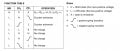
I've some basic questions regarding the Pinout Function of 4017.

1. If the RESET pin was connected to pin10 (5th seq. output)...
..the output will be from pin3 (1st seq. o/p) to pin7 (4th seq. o/p) only and back again to pin3 to pin7 and over and over again ?

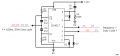
2. If the pin13 (Clock/latch enable) is held high the sequence will stop as far as the pin 13 is high ? What if it is not connected to either + or Gnd terminal ?

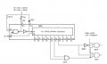
3. What will be the output duty cycle of each output
(i.e. from 1st seq. to 3rd seq. with the RESET pin connected to 5th seq. o/p) if the clock input has a 50% duty cycle square wave ?


Thank you ^_^
 

bertus

Joined Apr 5, 2008
22,270
Hello,

to question 1: Yes, there will be a pulse of several nanoseconds to reset the counter on the 5th output.

to question 2: see diagram ; hef 4017_clock_clear.jpg

to question 3: th duty cycle will be about 25 % high / 75 % low when you connect the 5th output to the reset.

Greetings,
Bertus
 

Attachments

Last edited:

mik3

Joined Feb 4, 2008
4,843
For 1:

Yes, it will repeat from pin 3 to pin 7.

For 2:

If pin 13 is not connected to anything (floating pin), because the chip uses CMOS technology you wont be able to tell if it will latch or not, it will be arbitrary. Thus, you have never leave pins floating on CMOS chips. If it was a TTL chip a floating input is accepted as a high logic by the chip.

For 3:

Check this site:

http://www.doctronics.co.uk/4017.htm
 

Thread Starter

JUAN DELA CRUZ

Joined May 27, 2008
121
Thank you guys for answering my queries.. ^_^

This was the 4017 diagram that confused me. I will use it together with a totem-pole from the output 1 & 3 (totem-pole not shown) to drive power MOSFET to have a Modified-sine wave (stepped-square wave) output from the transformer.
Help me to calculate the needed clock frequency and duty cycle to have an 60Hz/ 50Hz, stepped square wave output from the decoded output 1 & 3 as shown in this diagram.


Thank you ^_^
 

Attachments

Last edited:

bertus

Joined Apr 5, 2008
22,270
Hello,

The trick of this schematic is switching rising and falling edges.
With th 2 diodes from 0 and 2 they set the clock pulse to the other edge using th CE/ input.
The result is that you have a duty cycle of 1.5 clockpulses high and 2.5 clockpulses low.
The complete cycle takes 4 clockpulses so you need a 4 times higher frequency at the input.
For 50 Hz output you will need 200 Hz clock.
For 60 Hz uotput you will need 240 Hz clock.

Greetings,
Bertus
 

raybo

Joined Oct 18, 2008
22
your scheme will not work. was first the chicken then the egg. at power up nothing is set up. if the reset goes hi no clock and no count and no change. it may work sometimes by accident . do the karnaugh map that will tell you. it will work if you condition the reset during power up then yes it will count once and stop.
 

bertus

Joined Apr 5, 2008
22,270
Hello,

The Reset will work, C6 will be charged by R9 and go down to low level in a few miliseconds.
Then the counter will do his job as described by me.

Greetings,
Bertus
 

Thread Starter

JUAN DELA CRUZ

Joined May 27, 2008
121
Hello,

The trick of this schematic is switching rising and falling edges.
With th 2 diodes from 0 and 2 they set the clock pulse to the other edge using th CE/ input.
The result is that you have a duty cycle of 1.5 clockpulses high and 2.5 clockpulses low.
The complete cycle takes 4 clockpulses so you need a 4 times higher frequency at the input.
For 50 Hz output you will need 200 Hz clock.
For 60 Hz uotput you will need 240 Hz clock.

Greetings,
Bertus
Thank you sir for the info... ^_^

But, how can I turn-off the CD4017 when the battery voltage is low (approx. 11.8V) ?

Do I need to put "HIGH" at the RESET pin so that the CD4017 will stop from counting and prevent the output from "1" & "3" held "HIGH" (output "1" & "3" must be "LOW" when the battery voltage reached 11.8V).

BTW, do I need to ground the unused output pin of CD4017 ?

Thank you
 
Last edited:

pebe

Joined Oct 11, 2004
626
Juan,
There is an error in the circuit. CK and CE are the wrong way round.

With CK high, a -ve going pulse will be differentiated by C4.R7 and momentarily take CK low. CK will clock as the trailing edge of the differentated pulse returns to +V.

Similarly, CE clocks at the -ve trailing edge of the differentiated pulse from C5.R8 when the input is from +ve going input pulses.
 

Thread Starter

JUAN DELA CRUZ

Joined May 27, 2008
121
Juan,
There is an error in the circuit. CK and CE are the wrong way round.

With CK high, a -ve going pulse will be differentiated by C4.R7 and momentarily take CK low. CK will clock as the trailing edge of the differentated pulse returns to +V.

Similarly, CE clocks at the -ve trailing edge of the differentiated pulse from C5.R8 when the input is from +ve going input pulses.
I see.. the CK & CE was reversed.
Hence, this will be the right ckt. ? How about the unused output pin, it should be connected to the ground?

BTW, in which input pin must be held HIGH so that the CD4017 will stop from counting and prevent the output "1" & "3" HIGH upon stopping the decade counter IC? The CE or the RESET pin?


Thank you
 

pebe

Joined Oct 11, 2004
626
Your circuit is now correct. There are five unused output pins - all of them should remain unconnected.

Either RES or CE held high will stop it counting. But you should use RES, because if you use CE the count will not reset and it may have stopped when Q1 or Q3 was high.
 

Thread Starter

JUAN DELA CRUZ

Joined May 27, 2008
121
Your circuit is now correct. There are five unused output pins - all of them should remain unconnected.

Either RES or CE held high will stop it counting. But you should use RES, because if you use CE the count will not reset and it may have stopped when Q1 or Q3 was high.
Thank you Sir ^_^
 

bertus

Joined Apr 5, 2008
22,270
hello,

No, only the reset will be quicker.

Greetings,
Bertus

PS i am working on a counter decoder solution with shutdown for you if you want.
 

pebe

Joined Oct 11, 2004
626
Juan,You have shown the clocking frequency variously as 180Hz and 240Hz. The correct frequency is 2 × operating frequency. ie. 120Hz for a 60Hz inverter supply.
 

Thread Starter

JUAN DELA CRUZ

Joined May 27, 2008
121
Hello,

The trick of this schematic is switching rising and falling edges.
With th 2 diodes from 0 and 2 they set the clock pulse to the other edge using th CE/ input.
The result is that you have a duty cycle of 1.5 clockpulses high and 2.5 clockpulses low.
The complete cycle takes 4 clockpulses so you need a 4 times higher frequency at the input.
For 50 Hz output you will need 200 Hz clock.
For 60 Hz uotput you will need 240 Hz clock.

Greetings,
Bertus


Juan,You have shown the clocking frequency variously as 180Hz and 240Hz.
The correct frequency is 2 × operating frequency. ie. 120Hz for a 60Hz inverter supply.
*********************************************************

Hi guys.. which is the right clock ƒ needed to have a 50Hz/ 60Hz output from "1" & "3" in this ckt. ?


Thank you
 
Last edited:

pebe

Joined Oct 11, 2004
626
I have already just told you here, and previously on another forum.

As you know, I designed the circuit for you so I should know what I intended!
 

Thread Starter

JUAN DELA CRUZ

Joined May 27, 2008
121
I have already just told you here, and previously on another forum.

As you know, I designed the circuit for you so I should know what I intended!
I'm so sorry for that sir... honestly I'm not the one who first tested that ckt. that you'd gave me. A friend of mine who first tested it.
So, the right clock ƒ will be 120Hz for 60Hz output & 100Hz for 50Hz. For this reason, I'm came -up with an idea to use PWM controller IC (Osc.) like SG3524, TL494, etc. Using those IC's, I think the output voltage of the invertor will more regulated and compensate for battery voltage variation at the same time I think I can shut-down the PWM controller IC when the battery voltage is less 'coz it has some shut-down pin... hmmm not so sure... ^_^ But, currently I'm just reading their datasheets & application notes. As soon as I'm done with my ckt. I will post it here... for your suggestion ...or correction ^_^ 'coz you know I'm an undergraduate ^_^ Thank you.
 

Thread Starter

JUAN DELA CRUZ

Joined May 27, 2008
121
Hello,

Here is my probe of an oscillator for the inverter.

Greetings,
Bertus
Hi sir.. thank you so much for your effort ^_^ but I need an Osc. with variable duty cycle for that reason the output voltage of the invertor will compensate for battery voltage variation (i.e. 13.8V to 11.8V). I came-up with an idea of using PWM Controller IC such as TL494 or SG3524, etc.

What PWM controller IC (as Oscillator) do you think is well-suited in building this linear type MSW invertor together with CD4017 decade counter? ....TL494? ....or Sg3524/25?


Thank you
 
Top