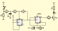
CD4013 circuit flips but doesn't flop

ericgibbs

Joined Jan 29, 2010
21,452
Hi Phil,
What type and quality is the push button switch are you using, some of the cheaper switches have a a lot of contact bounce.
E
OT: I am well, thank you, I hope you are also keeping well and busy.;)
 

Thread Starter

Philexium

Joined Oct 15, 2017
110
Hi Phil,
What type and quality is the push button switch are you using, some of the cheaper switches have a a lot of contact bounce.
E
OT: I am well, thank you, I hope you are also keeping well and busy.;)
Well the latest results are the following :
Only the solution from @Ian0 works fine : I have added to gates of a CD4093 to control the CLOCK and it works 100% fine

The solution from @crutshow gave random results
 

MrChips

Joined Oct 2, 2009
34,832
Since you already have a spare flip-flop, you may as well put it to work.
You will need a double throw push button for this.

Switch debounce with RS flip-flop.jpg
 

MrChips

Joined Oct 2, 2009
34,832
What are the full part numbers, including date codes, of the "faulty" CD4013 parts.
For comparison, also post the part numbers of the "good" 4013.

If you don't mind, post clear photos of the different parts.
 

Ian0

Joined Aug 7, 2020
13,145
YES!! for a CMOS input application. It may, or not, depending on unknowns. AND, consider that in the data sheet there is a fair voltage range where there is no promise of any particular result. There is a good reason for that.
That must be a very dirty circuit board or a very leaky capacitor!
 

Ian0

Joined Aug 7, 2020
13,145
What are the full part numbers, including date codes, of the "faulty" CD4013 parts.
For comparison, also post the part numbers of the "good" 4013.

If you don't mind, post clear photos of the different parts.
From my previous experience:
Philips, Toshiba = Good
SGS-Thomson, Texas =Bad
Motorola = can't remember (no Schmitt symbol shown on the datasheet)
 

MrChips

Joined Oct 2, 2009
34,832
I am curious if increasing the value of the series resistor to the LED made any difference.
Every CD4013B and MC14013B (i.e. B versions) that I have examined have buffered outputs.
 

MrAl

Joined Jun 17, 2014
13,711
Hi

I have designed a flip flop circuit with a CD4013 (See schematic) to control a LED.
When I press the switch, the circuit flips, the LED lights up
When I press it again, , it doesn't flop and the LED remains lighted up.
I have tested a lot of TI chips from 2 different suppliers with different date codes.
The problem is the same.

I have replaced them with other chips from Toshiba and it works fine.
I have a lot of TI chips in stock and would like to avoid throwing them away !

Any idea ?
Hello,

I see there have been a lot of replies that could help to fix this, but I have to ask are you stuck with using a CD4013 or can you use a different part number for the flip flop?

BTW I like your description of the problem, "Flips but won't Flop". Cute :)
 

MrChips

Joined Oct 2, 2009
34,832
The only 4013 I have on hand are Motorola MC14013BCP RQ8217.
MC14013B.jpg
I am testing the circuit posted by TS.

CD4013.jpg

My test circuit with 470 Ω output resistor "fails" differently.
When the pushbutton is pressed, the LED is lit.
When the pushbutton is released, the LED goes off.

If the output resistor is increased to 560 Ω or higher, the circuit toggles correctly.
 

MisterBill2

Joined Jan 23, 2018
27,606
Once again!! 220K is an excessively high pull down resistor for a CMOS input, if a circuit is to function with every brand of CMOS devices.
If you will not believe the specifications published then there is no way I can help !!!
 

Thread Starter

Philexium

Joined Oct 15, 2017
110
I am curious if increasing the value of the series resistor to the LED made any difference.
Every CD4013B and MC14013B (i.e. B versions) that I have examined have buffered outputs.
Hi @MrChips
I have increased the value to 10 k as I used a high luminosity LED.
Same problem with the CD4013 TI
OK with the TC4013 from Toshiba.
 

Thread Starter

Philexium

Joined Oct 15, 2017
110
Hello,

I see there have been a lot of replies that could help to fix this, but I have to ask are you stuck with using a CD4013 or can you use a different part number for the flip flop?

BTW I like your description of the problem, "Flips but won't Flop". Cute :)
Hello @MrAI

I have more than 30 CD4013 from TI in stock
The TC4013 from Toshiba works fine

Thank you for the "flips but won't flop" ... Yes the flop with the TI chips was ... a flop:)
 

MrChips

Joined Oct 2, 2009
34,832
I removed capacitor C1 and the flip-flop toggles.
This suggests that the problem could be related the the rise-time of the clock signal as already suspected.

Your solution is to use a better switch debounce circuit.

I don't have a problem with 220 kΩ pull-down resistors. Using a lower value would reduce the rise and fall time.
I kept C1 but replaced R1 with 33 kΩ. The flip-flop toggles properly.
 

sarahMCML

Joined May 11, 2019
698
I just built up the circuit on a breadboard with three different chips, and found that it worked better with the 100nF cap on the clock removed. I also had the clock input connected to the switch via a 1k resistor, purely because I ran out of jumpers and it was to hand!
I used the standard breadboard momentary push switch and found there wasn't much difference between a new TI CD4013B, a 1975 Fairchild 34013PC, or an even more ancient 1972 Solid State Scientific 4013AE version. They all toggled quite happily at both 5V and 10V, with a H.E LED with 22k in series to ground. There was the occasional switchbounce misfire though!
 
Top