CD4013 circuit flips but doesn't flop

Thread Starter

Philexium

Joined Oct 15, 2017
110
Hi

I have designed a flip flop circuit with a CD4013 (See schematic) to control a LED.
When I press the switch, the circuit flips, the LED lights up
When I press it again, , it doesn't flop and the LED remains lighted up.
I have tested a lot of TI chips from 2 different suppliers with different date codes.
The problem is the same.

I have replaced them with other chips from Toshiba and it works fine.
I have a lot of TI chips in stock and would like to avoid throwing them away !

Any idea ?
 

Attachments

Alec_t

Joined Sep 17, 2013
15,116
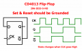
I think I read somewhere that chips from different manufacturers can differ in the way they behave when both R and S are high simultaneously. Just a long shot, but try tying the R and S of the unused flip-flop to ground instead of Vdd.
In theory the two flip-flops in the chip are independent, but who knows ......?
 

Ian0

Joined Aug 7, 2020
13,126
Some 4013s have a Schmitt trigger on the clock input, and some don't.
Philips (NXP) do and TI's don't.
The non-Schmitt trigger types don't like slow edges on the clock input, and tend to clock on both edges.
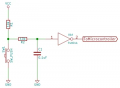
If you put a Schmitt trigger between switch and Clock input, it will work.
 

Thread Starter

Philexium

Joined Oct 15, 2017
110
I think I read somewhere that chips from different manufacturers can differ in the way they behave when both R and S are high simultaneously. Just a long shot, but try tying the R and S of the unused flip-flop to ground instead of Vdd.
In theory the two flip-flops in the chip are independent, but who knows ......?
Hi
Thank you I just tried it but the problem is the same
 

Thread Starter

Philexium

Joined Oct 15, 2017
110
Some 4013s have a Schmitt trigger on the clock input, and some don't.
Philips (NXP) do and TI's don't.
The non-Schmitt trigger types don't like slow edges on the clock input, and tend to clock on both edges.
If you put a Schmitt trigger between switch and Clock input, it will work.
Hi @Ian0

Good idea
I'll try it
 

crutschow

Joined Mar 14, 2008
38,481
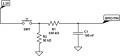
You could also try adding a 220kΩ resistor in series with the /Q output to the D input with 100nF to ground at the D input
The will reduce the sensitivity to any contact bounce.
 

Thread Starter

Philexium

Joined Oct 15, 2017
110
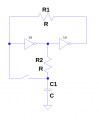
By the time you have done it, it would have been easier to use this circuit
View attachment 330070
Hi @Ian0

Thank you for the schematic !
Meanwhile I have checked the data sheets of NXP, TI and Toshiba.
Indeed the difference is the Schmitt trigger on the clock input that TI doesn't have ! I wouldn't have suspected it ...
I can only test it this evening or tomorrow morning and I'll keep you posted.
Thank you very much for this pertinent information

Philippe
 

Ian0

Joined Aug 7, 2020
13,126
Hi @Ian0

Thank you for the schematic !
Meanwhile I have checked the data sheets of NXP, TI and Toshiba.
Indeed the difference is the Schmitt trigger on the clock input that TI doesn't have ! I wouldn't have suspected it ...
I can only test it this evening or tomorrow morning and I'll keep you posted.
Thank you very much for this pertinent information

Philippe
I'd forgotten about Toshiba.
I used to synchronise signals to the mains using a very simple circuit (1M resistor connected from Live to the CLK input).
I remember that TI's devices didn't work but Philips did. But we bought most of our CMOS from Anglia Components who supplied Toshiba (so they must have worked and indeed a Schmitt trigger is shown on the datasheet).
SGS-Thomson is another to avoid.
The problem usually showed up by it clocking on both rising and falling edges. I can't remember if the toggle circuit worked or it didn't because we used the double-inverter circuit (about) to toggle a signal from a switch.
But ST and TI devices really don't like slow edges.
 
Last edited:

MrChips

Joined Oct 2, 2009
34,758
Three things I may suggest.

1) Increase the series resistor to the LED to 1k-2k Ω.
2) Try using a buffer to drive the LED.
3) Try a different switch debounce circuit.

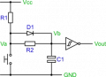
Here is just one example. Use 9 V supply instead of 3.3 V.

1724595665103.png

I don't know anything about rising edge sensitivity. If that is the problem then here are some examples.
Whatever Schmitt trigger you choose, make sure that it will operate on 9 V.

1724596029446.png


1724595820211.png
 

Thread Starter

Philexium

Joined Oct 15, 2017
110
I'd forgotten about Toshiba.
I used to synchronise signals to the mains using a very simple circuit (1M resistor connected from Live to the CLK input).
I remember that TI's devices didn't work but Philips did. But we bought most of our CMOS from Anglia Components who supplied Toshiba (so they must have worked and indeed a Schmitt trigger is shown on the datasheet).
SGS-Thomson is another to avoid.
The problem usually showed up by it clocking on both rising and falling edges. I can't remember if the toggle circuit worked or it didn't because we used the double-inverter circuit (about) to toggle a signal from a switch.
But ST and TI devices really don't like slow edges.
Hi again @Ian0

I had finally the time to add 2 gates of a CD4093 connected to the CLOCK and ... it WORKS :)
Yes I have now the proof that those TI chips don't like slow edges !
Thanks gain and have a nice evening
Philippe
 

Thread Starter

Philexium

Joined Oct 15, 2017
110
You could also try adding a 220kΩ resistor in series with the /Q output to the D input with 100nF to ground at the D input
The will reduce the sensitivity to any contact bounce.
Hi @crutschow
I was a little bit skeptical ...
Yes it works too (See Ian0 idea) :) Could you explain me how this R-C circuit works ?
Thank you !
 
Top