 Facebook
 Google
 GitHub
 Linkedin
Chris65536
- Joined Nov 11, 2019
- 270
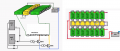
It's not shown on the Excel drawing, but I think each output pair is connected to one of the 8 output transistors shown on the lower left. He doesn't show the connections, but it looks like the vertical positions of the lines would match up.Even more confused now. Still don't understand why you're pushing one output against another.

")


