Cascaded OP-AMP Question (GBWP).

Russmax

Joined Sep 3, 2015
82
Here is an open loop response of an opamp that has a GBWP of 1e6:

View attachment 91579

Note Gain at 10Khz, 100Khz and 1MHz.

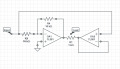
Closing the loop two different ways, note that the BW (when gain is down by -3db) is 500kHz for the gain of -1, and 1MHz for the follower. The BW of the difference is actually 666kHz, so the problem goals have not been met...

View attachment 91580
MikeML, try it with a capacitor parallel with R1, C = 1/(2*pi*100k*1MHz)
--Russmax
 

GopherT

Joined Nov 23, 2012
8,009
There's a way, but it seems like it's cheating.

GopherT and #12 both showed a circuit that almost works, except the inverting op amp only has 500 KHz BW.
Take that circuit and put a C in parallel with the 10K input resistor (R2 in GopherT's circuit) to create a zero in the inverting transfer function at 1 MHz. Just to make it still somewhat your work, I'm not going to tell you what value of C to use. You have to calculate that.

This will fight the 500 KHz pole of the inverting configuration and extend the frequency response of the inverting amp by 1 octave (doubling), when it bumps again against the unity-gain bandwidth. Then both the inverting and non-inverting op amps will have a BW of 1 MHz, and can add their gains together to get a gain of 2.

At least Spectre thinks so.

Regards
Well done sir. The question was too well crafted not to have a solution from my gut feeling. I also felt it was a bit of a trick question so a trick answer is needed (if you want to use the word trick). As said above, it is not a trick if constraints were not given to avoid the option. Again, well done.
 

crutschow

Joined Mar 14, 2008
38,529
Apparently the teacher doesn't know that the bandwidths of the inverting and non-inverting op amp configurations are different, even though they are both at the same gain.
It's a common mistake but a teacher should not make it.
I suppose it's a sad commentary on how someone with such a basic ignorance of the subject could end up teaching it. :confused:
 
Both at unity gain, one inverts. Doubles voltage to 1k load.


If the load can be floating as GopherT has it, then connect it between the output of the inverting stage and the input. The input has to be a voltage source, of course. If it isn't, the gain of the inverting stage won't be -R4/R2 anyway, so I think the input can be taken to be a voltage source.

With the same size cap across R2 as suggested by Russmax, the bandwidth is more than 1 MHz, and we're only using 1 opamp.
 

Attachments

Did you miss this part of my suggestion?

"With the same size cap across R2 as suggested by Russmax, the bandwidth is more than 1 MHz, and we're only using 1 opamp."
 

MikeML

Joined Oct 2, 2009
5,444
Did you miss this part of my suggestion?

"With the same size cap across R2 as suggested by Russmax, the bandwidth is more than 1 MHz, and we're only using 1 opamp."
I thought you were advocating that just eliminating the voltage follower would satisfy the 1MHz bandwidth requirement...
 

MikeML

Joined Oct 2, 2009
5,444
What result do you get with your circuit in post #31 if you include a 15.9 pF capacitor in parallel with your R1?
With R1=R2=10K, and C1=16pf, the gain is down only 2db at 1MHz. My conclusion; it takes a little less than 15.9pF to satisfy the -3db down at 1MHz.


In the sim, the progression is C1=4, 6, 8, 10pF as color of the plots follow the resistor color code... (yel = 8pF). I am guessing you dropped a factor of two from your calculation...


114d.gif
 
Last edited:
With R1=R2=10K, and C1=16pf, the gain is down only 2db at 1MHz. My conclusion; it takes a little less than 15.9pF to satisfy the -3db down at 1MHz.


In the sim, the progression is C1=4, 6, 8, 10pF as color of the plots follow the resistor color code... (yel = 8pF). I am guessing you dropped a factor of two from your calculation...
I noticed that it was about 2 times larger than needed. That's why I said "With the same size cap across R2 as suggested by Russmax, the bandwidth is more than 1 MHz, and we're only using 1 opamp."

Chuffed said "So according to his answer sheets, this was basically the set up." I wonder what exactly did the instructor give as the answer?

Chuffed, can you tell us?
 

Russmax

Joined Sep 3, 2015
82
He plugged in his calculations correctly, but the equations are wrong. This hook-up has different behavior than the hook-up with the bridged op amps. That configuration required one to get BOTH amplifiers to have a BW of 1 MHz.

In this configuration, only the Inv side of the load has a limited BW. The Noninv side has infinite bandwidth.

The total gain is 2 at low frequencies. 3 dB down is when the gain is 1.414. The Noninv side always has a gain of 1 at all frequencies. The total gain is -3 dB relative to 2 when the Inv gain is 1.414 - 1 = 0.414, or -7.656 dB. What value of C gives Inv gain of -7.656 dB at 1 MHz? From your simulation, it looks like the yellow curve, or 8 pF is the answer.

Regards
 

Russmax

Joined Sep 3, 2015
82
I noticed that it was about 2 times larger than needed. That's why I said "With the same size cap across R2 as suggested by Russmax, the bandwidth is more than 1 MHz, and we're only using 1 opamp."

Chuffed said "So according to his answer sheets, this was basically the set up." I wonder what exactly did the instructor give as the answer?

Chuffed, can you tell us?
Chuffed told us that in post #26. The instructor is apparently unaware that the inverting configuration only has BW of 500 kHz. He simply bridged the inverting and non-inverting amps to the load with no frequency shaping.
 
Top