Car battery monitor,

ArakelTheDragon

Joined Nov 18, 2016
1,366
This is a very complicated circuit for a battery monitor. Not to mention that assembler with PIC16F877A is not a good idea.
Why dont you use something like PIC16F506?

It will be better to output a LED (levels) when the battery is charged more. You need a few LEDs that will start 1 after another or 2 LEDs with a different color for charged and not charged.

Be carefull when playing with car batteries, they are working at 12V, 55A DC current and are dangerous!

EDIT:
If this is the MPLAB "XC8" compiler, I dont see the catch all header file "xc.h".
 

Thread Starter

Zun

Joined Aug 6, 2017
72
I have mikroProg for PIC Program,mer/Debugger and I never had problems with it.

99 USD. Is it much ? You get technical support and firmware updates when new devices are added. Works with mikroC/mikrobasic/mikroPascal Pro PIC/dsPIC/PIC32 Compilers.
OK, I want to up grades my pic kit first, and now waiting for order pic16f628a to add firm ware,
 

Thread Starter

Zun

Joined Aug 6, 2017
72
This is a very complicated circuit for a battery monitor. Not to mention that assembler with PIC16F877A is not a good idea.
Why dont you use something like PIC16F506?

It will be better to output a LED (levels) when the battery is charged more. You need a few LEDs that will start 1 after another or 2 LEDs with a different color for charged and not charged.

Be carefull when playing with car batteries, they are working at 12V, 55A DC current and are dangerous!

EDIT:
If this is the MPLAB "XC8" compiler, I dont see the catch all header file "xc.h".
Thank you ,i will try pic 16f877a first ,
 

jayanthd

Joined Jul 4, 2015
945
J4.000 , seller told me 4 mhz,it is correct j4.000?
Connect the RN2 resistor pad or resistors and try.

Are you telling that value is fluctuating or are you telling that display is not proper or both ?

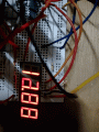
It seems you didn't use PIC16F877A. Which PIC you used ? My code and .hex file is for PIC16F877A.

Post high res image of the complete breadboard circuit.

Is the chip shown in the image is ULN2003A or is it resistor chip (330R) ?
 

Thread Starter

Zun

Joined Aug 6, 2017
72
Connect the RN2 resistor pad or resistors and try.

Are you telling that value is fluctuating or are you telling that display is not proper or both ?

It seems you didn't use PIC16F877A. Which PIC you used ? My code and .hex file is for PIC16F877A.
I know a little ,
 

jayanthd

Joined Jul 4, 2015
945
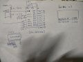
See circuits in previous posts. RN2 is a resistor pad (pull-up resistor) for 7 Segment display circuit.

ULN2003A has open collector outputs. In Proteus the RN2 resistor pad or (resistors) are needed but not sure about hardware. Add it and test the circuit working.
 

Thread Starter

Zun

Joined Aug 6, 2017
72
Yes
Connect the RN2 resistor pad or resistors and try.

Are you telling that value is fluctuating or are you telling that display is not proper or both ?

It seems you didn't use PIC16F877A. Which PIC you used ? My code and .hex file is for PIC16F877A.

Post high res image of the complete breadboard circuit.

Is the chip shown in the image is ULN2003A or is it resistor chip (330R) ?
Yes, i use Pic 16f877a, ula 2003a,330 resistor at rn1 only, 1 k resistor at seven seg all digit, 0.1 uf apasot at vdd and vss,
 

ArakelTheDragon

Joined Nov 18, 2016
1,366
Monitoring a battery voltage with an MCU is very difficult. You need to shut down the battery for some time, wait until the voltage stabilizes and then measure it. Its much better to use an analog system to measure the battery and then just record the result with an MCU.
 
Top