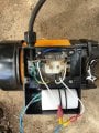
Capacitor wiring on pump

Thread Starter

gerryr1gerryr

Joined May 24, 2011
20
First post so I hope its in the right area.
Have a brand new ( Chinese made ) 3 stage 240V electric water pump.
Tried it out and it wirked just fine but power cord was too short.
Removed cover and replaced with a longer cable but when I tried to start it
I just get a "motor hum".
Removed capacitor anf tested and its fine at 20 uF.
I was sure I replaced the wires correctly but would appreciate it someone could check out the wiring
and see if there is and obvious error.

PS Motor manually turns over by hand.

Thanks
 

Attachments

MaxHeadRoom

Joined Jul 18, 2013
30,627
You could test the two windings to see if you have the cap in series with the higher resistance winding.
Alsp test by spinning the shaft as the power is applied, if possible.
Max.
 

Lo_volt

Joined Apr 3, 2014
370
What's the wire size gauge of the replacement cord? Is it the same size as the original? How much longer?
 
Last edited:

Thread Starter

gerryr1gerryr

Joined May 24, 2011
20
Thanks for the relpies.
Extended cord by one meter only using same gauge as original.

Motor starts fine when I give it a push start.

Cap is 415V 20uF and tests at exactly that on a Multi.

Also tried a 415V/40uf but made no difference.

Problem only occured when I reconnected new wiring to the motor which was made me think I had made an error in reconnecting the wiring somehow.

I am a bit of a silly old fart anf forgot to note the cap connections before I started.
 

MaxHeadRoom

Joined Jul 18, 2013
30,627
Sounds like the start/run cap is not connected, or in error.
You should have two winding's one will be a start, higher resistance of the two, the run the lower resistance.
The cap should be in series with the high resistance one, if both winding's are the same, then either can serve as start and run, but in reverse.
Max.
 

MaxHeadRoom

Joined Jul 18, 2013
30,627
Identify the wires coming out of the motor, should normally be three, two winding's in series with one connection being the centre tap (N).
Max.
 

Thread Starter

gerryr1gerryr

Joined May 24, 2011
20
The connection block on top of motor has 3 connections.
V1, U2, W
V1 Active (240V)plus Black wire to motor.
U2 White wire to motor and wire to Cap.
W Neutral(240V) plus Blue wire to motor plus wire to Cap.

Black wire to Blue wire 4 Ohms. (Not connected to connection block)
White wire to Blue 11 Ohms. (Not connected to connection block)
Hope this helps
 

MaxHeadRoom

Joined Jul 18, 2013
30,627
So it appears white to black should be 15Ω. Confirm.
If so I would have thought the Blue would be AC common (N), black AC L , and white would have the cap connected, the other end of the the cap to AC L.
This will depend on seeing the 15Ω total, if not show highest reading.
Max.
 

Thread Starter

gerryr1gerryr

Joined May 24, 2011
20
Confirmed White to Black is 15 Ohms.
I therefore assume the wiring would be as follows;

V1 Active and Black Motor Wire
W Neutral,Blue Motor Wire, and Cap 1
U2 White Motor Wire and Cap 2

Would this be correct ??

Thank You
 

MaxHeadRoom

Joined Jul 18, 2013
30,627
Normally the centre tap (Blue?) would be neutral, the Black AC, white the capacitor. the other end of the cap to AC
The OP shows one Cap?
Max.
 

Thread Starter

gerryr1gerryr

Joined May 24, 2011
20
Sorry for my confusion. I meant:
V1 Active and Black Motor Wire
W Neutral,Blue Motor Wire, and Cap (one End)
U2 White Motor Wire and Cap (other End)

So the cap would be connected to W (Neutral) and U2(White Motor Wire)
 

MaxHeadRoom

Joined Jul 18, 2013
30,627
The lower resistance winding would normally be connected across the incoming supply, the higher resistance start winding would have the capacitor in series with it.
So you would have the centre terminal of the pair of winding's (blue?) Neutral
Max.
 
Top