Capacitor voltage drops, negative voltage.

Thread Starter

cmisip

Joined Sep 23, 2017
89
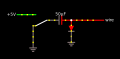
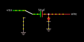
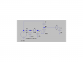
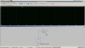
I am not understanding how the voltage in this simulator drops to the specific value of -2.93 volts when the switch is on the 5V supply and then -7.93 when the switch is on the GND. I am using the falstad circuit simulator.

I thought the capacitor has a charge of 5 - .8 volts = 4.2 volts. So the voltage at the anode of the diode should be .8 volts. Then when I drop the plate A voltage to 0 volts, then plate B should go from .8 to ( .8 -5 ) -4.2 volts.

Thanks,
Chris
 

Attachments

  • 307 bytes Views: 28

OBW0549

Joined Mar 2, 2015
3,566
I plugged your text file into that simulator, but it didn't appear to do anything. I'm not familiar with the tool, and am not willing to take the time to decipher what it's doing.

Maybe someone familiar with Falstad can help you.

(NOTE: most of the people here on AAC use the LTSpice simulator, so if you want the most/best help here, it would benefit you greatly if you would use it, too; it's kind of our "common language." I don't think too many here, other than raw newbies, use this "Falstad" thing.)
 

crutschow

Joined Mar 14, 2008
38,481
I thought the capacitor has a charge of 5 - .8 volts = 4.2 volts. So the voltage at the anode of the diode should be .8 volts. Then when I drop the plate A voltage to 0 volts, then plate B should go from .8 to ( .8 -5 ) -4.2 volts.
That sounds correct.

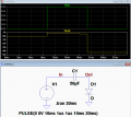
Below is the LTspice simulation of the circuit, which corresponds to your analysis.

upload_2017-11-15_16-2-17.png
 

neonstrobe

Joined May 15, 2009
200
the only reason the voltages would be different is if the capacitor has an initial charge, but you did not indicate that. Your original voltages could be correct if the initial charge is 7.93V (x 50uF) as the diode would not have any effect, as the diode side of the capacitor is then -2.93V, which will not turn it on. The final voltage will be -7.93 when switching from +5 to ground (the second diagram is first). In simulators you have the option of specifying an initial voltage on a capacitor or open circuit, which can be important.
 

Thread Starter

cmisip

Joined Sep 23, 2017
89
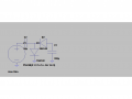
I did not specify an initial voltage charge on the capacitor when I setup the simulator. I redid the simulation in falstad, replacing the switch and 5v, 0v source with a pulsed square wave generator and ended up with the same negative voltages. I am thinking that this is a simulator bug. Anyway, I decided to simulate this with LTspice and added a few things. I am trying to understand how it works. So far this is what I came up with. I'll adapt the convention of left capacitor or superior capacitor plate is plate A.

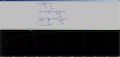
As I mentioned previously, the charge on C2 would be 5 volts - .8 or 4.2 volts. Dropping plate A of C2 from 5 Volts to 0 would cause plate B to drop from .8 to -4.2 volts. D2 anode is connected to plate A of C1. I would assume that plate A and B of C1 both have 0 volts. When the voltage at plate B of C2 is .8 ( which is the state of the plate B of C2 when the square wave is at 5 volts), then D2 is reversed biased so plate A of C2 would have 0 volts. It will maintain this voltage until plate B of C2 voltage reduces to -.8 volts at which point D2 is forward biased. D2 will drop the .8 volts and the voltage on C1 plate A will be 0. At -.9, the voltage on C1 plate A will be at .1, etc. So the voltage that would be seen at plate A of C1 would range from 0 to -3.4 volts ( always lagging the voltage of C2 plate B by .8 volts). C1 plate B is connected to GND and so it cannot move and will remain at 0 volts. Increasing or decreasing the voltage on plate A of C1 would then have the effect of charging ( when its voltage is decreased to -3.4 ) and discharging ( when its voltage is increased to 0 volts. So when plate A's voltage is increased to 0 volts, the -3.4 volts stored is released on the plate A side, in effect smoothing the voltage fluctuation resulting in a steady -3.4 volts. I think there is a flaw in my analysis. Why do I need D2? Can't C1 perform the smothing of the voltage fluctuations without it? If I remove D2, the voltage on C1 plate A fluctuates from 0 mv to 240 mv.

Thanks,
Chris
 

Attachments

Thread Starter

cmisip

Joined Sep 23, 2017
89
Its allaboutcircuits.com 's negative voltage generator circuit. Although I see that this can be finitely (dont know the limit) recursed by introducing the negative voltage output of the preceeding stage as the GND of the next stage thereby increasing the capacitor charge with each stage.

Chris
 

Attachments

Thread Starter

cmisip

Joined Sep 23, 2017
89
If D2 is not there:
Does capacitive voltage division work when the source is a square wave? I am trying to figure if that is what's happening or if this is a case of series capacitance. The diode pointing to ground complicates the analysis.

Chris
 

Thread Starter

cmisip

Joined Sep 23, 2017
89
I missed something pretty basic. The diode is apparently required for smoothing the square wave. It is apparently necessary to stop the reverse flow of current. I thought all I needed was the capacitor. For the negative voltage generator, the diode must point to the left as positive voltage is being blocked. I thought that if a voltage fluctuated from 0 volts to 5 volts, the capacitor charges on 5 volts and discharges on 0 volts if one of the plates is held at GND. I looked at the voltage graph with and without the diode and the only difference I can tell is with the diode, the voltage is less by the amount of the diode voltage drop. The capacitor is exposed to the same voltage fluctuations ( less the diode drop if a diode is used ) with or without the diode but smoothing only happens when the diode is present. Does anybody know why?

The green lines represent the voltage at the top of the capacitor without a diode. The blue line represents the voltage at the top of the capacitor with the diode in place.
 

Attachments

Thread Starter

cmisip

Joined Sep 23, 2017
89
The only thing I can think of is that the pulsed voltage source is actively driving the circuitry so it's output really is unmodifiable ( it will always output the square wave at its electrodes ). On the 0 volt phase of the pulsed voltage source, it can pull the capacitor charge and use it all up as anything that is directly connected to it must be pulled all the way to zero volts. With the diode, it can't pull this charge to zero ( positive voltage on the anode cannot travel to the pulsed voltage source's 0 volt terminal ) and hence it sits on the diode's anode, filling the gaps between the 5 volt peaks. The diode presents a modifiable copy of the source.

Chris.
 

WBahn

Joined Mar 31, 2012
32,786
The behavior of the circuit is fairly easy to understand.

Let's assume that the capacitor is initially uncharged and connected to ground (on the left side). Now it is switched to the 5 V terminal. Initially both terminals will be at 5 V because voltage can't change instantly across a capacitor. This means that the diode is forward biased (we'll ignore the need for some kind of current limiting element and assume the diode performs this task in some reasonable way). A current will flow into the capacitor reducing the voltage on the right side until the diode turns off at somewhere around 0.5 V or so (it won't actually "turn off" until it gets to 0 V, but the current below about 0.5 V will probably be low enough that we can ignore it over reasonable time frames).

So now we have about 4.5 V across the capacitor and essentially zero current flowing in it. Now the switch is moved back to ground. The left side of the cap goes to 0 V and, because the voltage across a capacitor can't change instantly, the right side goes to -4.5 V. This reverse biases the diode, so no current flows. Thus the output voltage will stay at -4.5 V (or something close) unless something is connected to the output that can supply current to discharge the capacitor.

If the diode hadn't been there (or if it had been a resistor), the capacitor would have quickly discharged after moving the switch.

EDIT: Correct typo spotted by AlbertHall -- thanks!
 
Last edited:

Thread Starter

cmisip

Joined Sep 23, 2017
89
Thanks for the replies.

Your analysis confirms what I was thinking as far as D1 is concerned. What do you think about the analysis as far as D2 is concerned.

So far I think I learned the following concepts (maybe):

1. A capacitor resists a force that is changing its state.
--> If a capacitor is connected to a battery source, the plate that is connected to the positive terminal will fill up with positive charges, becoming a reverse battery of sorts such that when its potential on the positive plate equals the source positive voltage, there will be no potential difference along its connection to the battery and hence no current will flow. Current only flows up to the point that the potential is equal. We can think of a "reverse current" that is summing with the forward (battery) current.

2. A capacitor tries to conserve its charge. It does so by trying to replicate (successfully or unsuccesfully ) the potential change on one plate onto the other plate.

--> When the capacitor plate A is presented a voltage, the capacitor plate B will adjust the same amount and direction so that if I put 5 volts on plate A, plate B will be whatever its existing potential is plus 5 volts. This is the INSTANTANEOUS or IMMEDIATE effect. Given sufficient time, the charge on plate B will change depending on the effects of components on that side.

Case a.
if there is a diode pointing to GND, the 5 volts will forward bias the diode until there is only about .65 volts difference between plate B and GND, in which case the diode open circuits and the potential on plate B will thus be .65 volts. This state is now the LATE or EQUILIBRIUM state. This leads to a charge of plate A ( 5 volts ) minus plate B (.65 volts) = 4.35 volts.

Case b.
If the component attached to plate B is a resistor to GND, then the resistor is going to pull plate B voltage down to GND ( 0 volts ), leading to a charge of 5 volts. The resistor will also have the effect of limiting current and hence increasing the time before the capacitor achieves this EQUILIBRIUM state.

Case c.
If plate B is attached directly to a fixed potential such as GND, the instantaneous effect would still pull plate B voltage up by 5 volts but it is immediately pulled down to 0 volts, causing the capacitor to charge 5 volts.

Case d.
If plate B is not connected to anything, its INSTANTANEOUS voltage of 5 volts will remain which means that the capacitors's charge is zero volts.

3. To smooth a fluctuating voltage, you need both a diode and a capacitor connected to GND even if the voltage fluctuates in magnitude in one direction only ( already rectified ). Rectifier circuits already have a diode before the smoothing capacitor. I thought that they were only necessary for rectification. But I now realize that they are necessary to keep the charge leaving the capacitor from being pulled to ground.

4. Smoothing a voltage also requires that one end of the capacitor be tied to GND or perhaps any fixed potential. This is so the capacitor reacts by increasing or decreasing the potential on the plate that is "movable". If the voltage on the plate that is "movable" causes the difference between plate A and B potential to increase, then the capacitor is charging. Otherwise it is discharging.

This is awesome. Its really looking like the best way to analyze circuits is to spot the subcircuits that comprise the circuits. D2 in the original schematic was really part of the smoothing circuit. Its really not necessary to analyze the possibility of this being a series capacitance or capacitive reactance voltage division which just complicates the analysis. Although following that line of thinking would probably result in the same analysis in a long about way.

To complete all the questions posted here I was wondering if somebody could answer the following:
Does capacitive voltage division work on square waves?


All these concepts are tested in this schematic.

upload_2017-11-23_9-16-18.png

Thanks,
Chris
 
Last edited:

WBahn

Joined Mar 31, 2012
32,786
Your use of descriptions like, "the positive terminal fills up" is troubling and makes me think that you haven't quite gotten the basics yet.

Except for very unusual, generally difficult to create situations, the total charge on a capacitor as a whole is essentially zero. Whenever an electron is added to one plate, one is removed from the other. Whatever charge ends up on one plate, the negative of that charge ends up on the other plate. The net total charge is always zero (or so close to it as to not matter for nearly all purposes).

Because energy storage in a capacitor is related to the charge separation on the plates, the charge separation can't change instantly, since energy must be conserved and hence charge can't change instantly. Since the voltage across a capacitor is proportional to the charge separation on its plates, this also means that the voltage across a capacitor can't change instantly. THIS is what results in the very useful property that whenever you change the voltage on one plate of a capacitor instantly (or very, very quickly), the voltage on the other plate changes just as quickly and by essentially the same amount.
 

Thread Starter

cmisip

Joined Sep 23, 2017
89
Your use of descriptions like, "the positive terminal fills up" is troubling and makes me think that you haven't quite gotten the basics yet.
Would it be accurate to restate it this way:
If a capacitor is connected to a battery source, the plate that is connected to the positive terminal will fill up with a positive charge while the opposite plate fills up with negative charge, becoming a reverse battery of sorts such that when its potential on the positive plate equals the source positive voltage, there will be no potential difference along its connection to the battery and hence no current will flow.

Because energy storage in a capacitor is related to the charge separation on the plates, the charge separation can't change instantly, since energy must be conserved and hence charge can't change instantly.
The concept of energy conservation in capacitors is still a little fuzzy to me. I do realize that it will take some time for electrons to travel from the source to the capacitor so the final potential on the capacitor will be realized after a bit of time. That's why I thought of an INITIAL state and a FINAL state. Does energy conservation mean that the capacitor tries to maintain a zero net charge all the time and therefore its response is to change the second plate in the same direction and magnitude of the change in the first plate?

Thanks,
Chris
 
Top