Capacitor Inductor Help

Thread Starter

cgha20@yahoo.com

Joined Oct 21, 2009
82
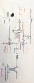
Need help determining what this circuit is doing. L2 is replaced for a short. I know the 150kHz square wave switches the 36VDC.what does the waveform look like with this cap and in series w transformer primary?
 

Attachments

Thread Starter

cgha20@yahoo.com

Joined Oct 21, 2009
82
i have picked 0.1uF cap and inductance on primary to be 12.5 uH. This gives resonance of approximately 150kHz. Is this correct. Does this circuit give me a sine wave at the original 150k frequency. please help
 

#12

Joined Nov 30, 2010
18,224
I predict bad things.
The basic premise of this circuit is that 150KHz arrives through 100 ohms and turns the first Q6 and the bottom Q6 on and off simultaneously.
When the input voltage goes to zero, the first Q6 turns off and R29 (10k) ohms tries to turn the upper Q6 on. 10K is too much resistance. The only saving grace is that 36 volts is way more than enough to turn that transistor on, even with a slow gate drive.
If the input frequency ever stops, the gate voltage promptly punches through the gate-source junction with 36 volts on a 10V or 20V limit. (I couldn't find that exact transistor to declare the gate voltage max for sure.)

L2 is there to keep the switching noise out of the power supply.
C30 is just big, so it doesn't hamper current flow by much.
Your 0.1 uf and 12.5 uH calculate to resonance at 142 KHz. That's 95% of your declared frequency, so probably close enough.
An excellent, high frequency transformer would pass the signal as a square wave, but a 300 watt power transformer is not an excellent, high frequency device, so it's going to make the square wave look a lot more like a sine wave, especially if you resonate the secondary at 150 KHz with a capacitor.

I don't know what your goal is, but I predict a crash and burn.
 
Top