Hi
Thanks for your reply, it really matters if you can understand the circuit, not sure what you mean " Text abbreviations", the only one I can see if that is an abbreviation, is the letter "N" meaning Neutral ! .
PS: I am not a Electronic Engineer, just a common Electrician trying to stop stuff going to landfill .
Cheers and thanks for looking anyway.
Spike
Here are some starting points to drawing schematics.
The rules are simple, and you don't need to learn EVERY component symbol to get started, just the basics.
it's the international language of electronics, it's very precise and communicates ideas clearly.
Here are some starting points to drawing schematics.
The rules are simple, and you don't need to learn EVERY component symbol to get started, just the basics.
it's the international language of electronics, it's very precise and communicates ideas clearly.
Hi
Thanks for that, I would just need to make sure that the info in my original drawing is correct for me to convert to a proper schematic, I have a couple of programs I can use (Autodesk Eagle premium and DipTrace ) have them but not used them , I done the one I posted on here with Smartdraw ! , but obvious I wasn't very smart using it !
Imagine if everyone made their own way of notating music or system of alphabets? It would be more cryptology than communication. A standardized format makes communication clear so we can quickly and easily see what's going on in the circuit. Do what you like for your own circuits... use pictures, short hand.... etc. but you may find that the convention works very well even if you went back after years of seeing the circuit, it is apparent without wondering what the pictograms are conveying.
Here are some starting points to drawing schematics.
The rules are simple, and you don't need to learn EVERY component symbol to get started, just the basics.
it's the international language of electronics, it's very precise and communicates ideas clearly.
It's a step in the right direction... There are some issues with it.
1. You should connect all the lines especially if it fits on the same page.
2.The BJT should be connected and not just labeled.
3. Label your voltages - AC1 - what does that mean? 120V, 240VAC... 24VAC???
4. Use a ground symbol to indicate ground... this way they do not all need to be connected
5. Values matter - label the resistor, cap, vales and include part numbers... I have no idea what those Zener voltages are
Good try, hopefully you're take this as feedback that helps you improve and not an attack.
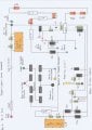
I would love to hear the reasoning behind all the diodes in your circuit. I haven't combed through it but on a quick scan it looks excessive and unnecessary. Here's a cropped version which makes it easier to see and read:
It's a step in the right direction... There are some issues with it.
1. You should connect all the lines especially if it fits on the same page.
2.The BJT should be connected and not just labeled.
3. Label your voltages - AC1 - what does that mean? 120V, 240VAC... 24VAC???
4. Use a ground symbol to indicate ground... this way they do not all need to be connected
5. Values matter - label the resistor, cap, vales and include part numbers... I have no idea what those Zener voltages are
Good try, hopefully you're take this as feedback that helps you improve and not an attack.
I would love to hear the reasoning behind all the diodes in your circuit. I haven't combed through it but on a quick scan it looks excessive and unnecessary. Here's a cropped version which makes it easier to see and read:
Hi
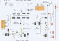
I hope this is a better one, I have not connected the Transistor because I am a little confused as to the connection I think is a PNP but it does not seem to fit the flow of the drawing , could be wrong, the lettering are correct as i Emitter,Collector,Base.
I could not really fit the Motor winding into the drawing I am sure there is a way to enlarge the sheet to do that !, so I have just really botched cramming it into the drawing .
Any comments as to if there is any mistakes in it would be highly appreciated .
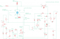
The circuit appears to be for a shredder and the capacitor appears to be connected across a relay coil as a chatter preventer. it may also affect the operating speed of the stall detector.
Why are you wanting to replace that capacitor? I would try to get one closer to the original value for that location. A higher voltage rating would be OK, though.
And the total panic mode of the comments about working with a 240 volt circuit is really out of place. Once an individual knows how to work around live circuits they can do it safely. In addition, did the TS ever say they were working on it live? I may have missed that because of all the noise about the drawing.
While the pictorial circuit was non-conventional it was quite possible to follow the circuit and see what was going on. The attack pile-on was certainly not needed.
And I am still wondering why the TS believes that capacitor needs to be replaced.
This was the original post .
“ Paper Shreader Fault, not running”
Switched it on then I was getting my meter out to test voltages , when I heard a buzzing sound so switched it off, then I switched on again to see what it was that was buzzing ,while I was listening it started up, held the 2 IR bulbs next to each other and it stopped, pulled them apart and the buzzing started then it started to run
I clipped the IR bulbs next to each other with a gap put a piece of paper in between nothing straight away, after a couple of seconds again it started to buzz then it started up ! “
Was informed to replace the 3 E Caps .
Spike
It’s better because more things are labeled, if you want to improve your skills recommend studying other schematic. It’s not bad for reverse engineering a board... I had forgotten that we were trying to fix it. Did you try your caps?
 Facebook
 Google
 GitHub
 Linkedin