Facebook
 Google
 GitHub
 Linkedin


Hello everyone.
I'm analyzing this circuit but I'm having a difficult time understanding how a part of it works.
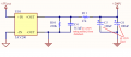
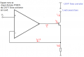
I have basically a 2 stage circuit, A and B. Stage A (Attachment 1) is a 5 to 200V converter and stage B is a constant current sink (Attachment 2). Stage B will use the 200V as the voltage compliance, so it can apply a current of 20 to 100mA(max) to a load resistor of up to 1kO. The ON time is small, with pulse width of 200-500µs max, and at a frequency of 20-100Hz.
My question is with the 5-200V converter. (Here is the datasheet http://www.datasheets360.com/pdf/5050517326450757206). A 200V converter was used. The datasheet says a 0.1µF-1000V capacitor is needed at the output to prevent surge. From the paper Im reading: "R10 ensures a minimum load for the 200 V converter. The converter has a maximum output of 6.25 mA, and R11 ensures the current is always below this amount."
If the converter sources only 6.25mA max, how do they manage to source 200V @ up to 100mA?
Im pretty sure it has to do with capacitors C5 and C6 from attachment 1, which are actually pretty big (100µF, 350V) , so they must be able to store a lot of energy. I think that they would have to charge the capacitors first, then turn of the converter, act as a Voltage source for a couple of pulses, then charge them again with the converter and so on.
If this is the case then how can I determine the amount of pulses that the capacitors provide before they need to be charged again?
If my question isn't clear, please let me know.
Any help appreciated! Thanks.
I'm analyzing this circuit but I'm having a difficult time understanding how a part of it works.
I have basically a 2 stage circuit, A and B. Stage A (Attachment 1) is a 5 to 200V converter and stage B is a constant current sink (Attachment 2). Stage B will use the 200V as the voltage compliance, so it can apply a current of 20 to 100mA(max) to a load resistor of up to 1kO. The ON time is small, with pulse width of 200-500µs max, and at a frequency of 20-100Hz.
My question is with the 5-200V converter. (Here is the datasheet http://www.datasheets360.com/pdf/5050517326450757206). A 200V converter was used. The datasheet says a 0.1µF-1000V capacitor is needed at the output to prevent surge. From the paper Im reading: "R10 ensures a minimum load for the 200 V converter. The converter has a maximum output of 6.25 mA, and R11 ensures the current is always below this amount."
If the converter sources only 6.25mA max, how do they manage to source 200V @ up to 100mA?
Im pretty sure it has to do with capacitors C5 and C6 from attachment 1, which are actually pretty big (100µF, 350V) , so they must be able to store a lot of energy. I think that they would have to charge the capacitors first, then turn of the converter, act as a Voltage source for a couple of pulses, then charge them again with the converter and so on.
If this is the case then how can I determine the amount of pulses that the capacitors provide before they need to be charged again?
If my question isn't clear, please let me know.
Any help appreciated! Thanks.
Attachments
-
 47.7 KB Views: 29
-
 46.7 KB Views: 30
Last edited: