capacitor calculation

Thread Starter

mahmut_kelesoglu

Joined Aug 12, 2022
67
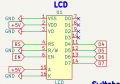
Hi. I have a 7805 regulator circuit that drops 17 volts to 5 volts. When I connect 17 volts voltage supply, ı can read 5 volts at the output. I need to control a LCD circuit with pic16f877a microcontroller. When I connect my regulator to that circuit, the read 5 volts value drops to 3.2 volts and oscillates between 3.2V and 3.1V. So, I couldn not be able to light on my LCD. I think my capacitor values that on regulator circuit are not right. My regulator circuit does not give 5 volts when ı connect lcd circuit. but, it gives 5 volts when nothing connceted. what is my problem? thanks for your helps.
 

AlbertHall

Joined Jun 4, 2014
12,343
Welcome to AAC, @mahmut_kelesoglu
What capacitors do you have on the input and output?
The datasheet rcommends 0.33uF on the input and 0.1uF on the output and note that they should be connected very close to the regulator pins.
 

Thread Starter

mahmut_kelesoglu

Joined Aug 12, 2022
67
Welcome to AAC, @mahmut_kelesoglu
What capacitors do you have on the input and output?
The datasheet rcommends 0.33uF on the input and 0.1uF on the output and note that they should be connected very close to the regulator pins.
ı have 100uF at input, and at output ı have tried some combinaitons such as 1uF, 10nF with 1uF, etc. Whatever ı try, ı read 5 volts when nothing connected, read 3.2 or 2.8 volts when my load is connected. also, according to your note, ı always connect caps close to the regulator.
additionally, my load has 4.1k ohms resistance. ıs that necessary when calculating caps values?
 

Ian0

Joined Aug 7, 2020
9,667
Where does the 17V come from?
what is the voltage at the INPUT of the regulator when you have 3.2V at the output?
 

Audioguru again

Joined Oct 21, 2019
6,671
He did not say the input is 17VDC. Since he has a 100uF capacitor on the input of the 7805 regulator then I suspect the 17V is
rectified 12VAC (13.1VAC with no load) and the 100uF is much too small for the current.

Why heat the 7805 with the very high 17V?
I am waiting to see the schematic.
 

Thread Starter

mahmut_kelesoglu

Joined Aug 12, 2022
67
Actually ı built my rectifier circuit on breadborad with jumpers. So, it is a litte bit complicated. I will send handwrited schematic.
My lcd circuit is built on PCB, but I couldnt be able to send that PCB before monday.
 

WBahn

Joined Mar 31, 2012
29,976
Where is your 17 V input coming from? Is it AC or DC? Is it possible to get lower, say something in the 8 V to 10 V range?

Do you have access to an oscilloscope so that you can see what is actually happening to the regulator output? If not, can you measure the current draw on the input supply?

My guess is that there is something wrong with your LCD circuit and it is drawing much more current than it should, forcing the regulator to go into short-circuit current limiting.
 

Thread Starter

mahmut_kelesoglu

Joined Aug 12, 2022
67
Where is your 17 V input coming from? Is it AC or DC? Is it possible to get lower, say something in the 8 V to 10 V range?

Do you have access to an oscilloscope so that you can see what is actually happening to the regulator output? If not, can you measure the current draw on the input supply?

My guess is that there is something wrong with your LCD circuit and it is drawing much more current than it should, forcing the regulator to go into short-circuit current limiting.
ı can measure the input supply but ı think your guess is not correct. because the regulator has 2.2 A for short circuit limit. the lcd couldnt be draw that much current, ı think.
 
Top