 Facebook
 Google
 GitHub
 Linkedin
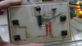
Hi guys, i am trying to build a remote controlled car, using a RF TX RX 315 Mhz Module, with HT12 decoder and encoder and a L293D Motor Driver, it's a pretty simple circuit, but i am facing some problems, i mounted the receiver circuit on a breadboard, there are pictures uploaded to imgur down below, then i mounted the transmitter circuit on a drilled pcb that i bought here in my town. The thing is when i press the button that controls the motor, it spins forever, it does not stop, and the led that indicates transmission between the RF modules, goes off, like something is transmitting to him to keep spinning, i measured the voltages at the controls pin at the L293D and it's low when it should be high, because i am not pressing the button, so it never stops spinning. Can anyone tell me, what the problem is ? I tried a lot of things, at the drilled PCB i checked for continuity at every single trail and there is no trail touching another trail, so there it's fine i believe. I tried to put a lot of 0.1uF ceramic capacitors to reduce some noise, but it changes nothing. I'm new to electronics, so i may be committing a mistake and i dont even know... if anyone could take a look. Also i am locked to these devices that i am using at the circuit. Another thing to put here, is that i am using a LM7805 to reduce the voltage to 5v at both the transmitter and the receiver. HELP!
http://i.imgur.com/f4S0hvZ.jpg - TOP VIEW from the Breadboard with the receiver circuit.

http://i.imgur.com/oQW4FHq.jpg - SIDE VIEW from the Breadboard with the receiver circuit.

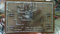
http://i.imgur.com/Gmx4i56.jpg - Transmitter circuit.

http://i.imgur.com/jD1gTAn.jpg - Soldering on the drilled PCB.

http://i.imgur.com/91pd0ZB.jpg - Transmitter SCHEMATIC.

http://i.imgur.com/wqY8LPG.jpg - Receiver SCHEMATIC.

I think i didnt forgot anything.
http://i.imgur.com/f4S0hvZ.jpg - TOP VIEW from the Breadboard with the receiver circuit.
http://i.imgur.com/oQW4FHq.jpg - SIDE VIEW from the Breadboard with the receiver circuit.
http://i.imgur.com/Gmx4i56.jpg - Transmitter circuit.
http://i.imgur.com/jD1gTAn.jpg - Soldering on the drilled PCB.
http://i.imgur.com/91pd0ZB.jpg - Transmitter SCHEMATIC.
http://i.imgur.com/wqY8LPG.jpg - Receiver SCHEMATIC.
I think i didnt forgot anything.
Attachments
-
 787.3 KB Views: 17
 -
 734 KB Views: 16
 -
 994.4 KB Views: 15


