Facebook
 Google
 GitHub
 Linkedin
The chip I am trying to use (picture with astable mode diagrams):
http://www.555-timer-circuits.com/operating-modes.html
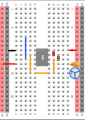
Here is my breadboard so far with this timer 555 chip:

I want to use astable mode, but am unsure how to proceed. I want to drive a clock pulse to some
D flip flops on the breadboard. No one ever taught me how to hook up capacitors and resistors on the breadboard and I am no self teacher. I used a logic probe, but there is no pulsing output at pin 3 like I think there should be, just low voltage. For R1: 220ohm, R2:100k ohm, C: 10uF, second capacitor: 0.01uF. Again there is no output at all, low voltage, and also 220ohm resistor is heating rapidly.
Any help is greatly appreciated!
http://www.555-timer-circuits.com/operating-modes.html
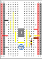
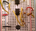
Here is my breadboard so far with this timer 555 chip:
I want to use astable mode, but am unsure how to proceed. I want to drive a clock pulse to some
D flip flops on the breadboard. No one ever taught me how to hook up capacitors and resistors on the breadboard and I am no self teacher. I used a logic probe, but there is no pulsing output at pin 3 like I think there should be, just low voltage. For R1: 220ohm, R2:100k ohm, C: 10uF, second capacitor: 0.01uF. Again there is no output at all, low voltage, and also 220ohm resistor is heating rapidly.
Any help is greatly appreciated!