Cannot fool a servo tester circuit

Thread Starter

djacob7

Joined Mar 25, 2013
5
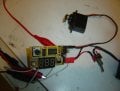
I'm trying to make a servo tester drive the servo back and forth faster. As is it drives the servo at about 1Hz, and I'd like to make it go about 2Hz.
The tester has a pot for manual positioning, and a switch for auto mode where it will drive the servo back and forth.
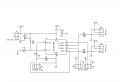
I thought to fool the circuit by applying a higher voltage to the pot wiper to make it go faster, but no dice - it won't go faster.
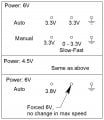
Below is a table of the supply voltage, fixed pot voltage, and wiper voltage.

Any idea why the max speed doesn't change with voltage?
 

Attachments

jpanhalt

Joined Jan 18, 2008
11,087
First what type of servo? Is it an industrial servo or typical hobby type?

If it is a typical hobby type, that is not how to control its speed. Increasing the voltage to the servo itself will increase speed a little, but basically they are fixed speed which depends a little on how much drag or friction is in the system. You can slow them down using another method entirely.

John
 

Alec_t

Joined Sep 17, 2013
14,280
Post the schematic of your servo tester. Changing a resistor or capacitor value may be all that is necessary.
 

djsfantasi

Joined Apr 11, 2010
9,156
Looks like a microcontroller based solution. In that case its likely that to change the speed, you would have to modify the code. I don't see any programming pins, so it may not be able to be reprogrammed, without possibly some kludge.
 

MaxHeadRoom

Joined Jul 18, 2013
28,617
The speed is decided by the PWM signal. With centre posn being 50% pulse.
I assume a shorter posn on the positioning arm does not give you the operation speed you need?
There are quite a few PWM servo tester circuits out there that you could increase the base PWM frequency to try it.
Max.
 

jpanhalt

Joined Jan 18, 2008
11,087
I think there are two aspects to "speed" in this case. The first is the speed that a servo moves when commanded from one position to another as a step function. For example, the time it takes a servo sitting at 1.5 mS to change position after receiving a pulse of 2.0 mS. That speed can be affected by voltage to the servo's supply pins. The second, which I think applies here after seeing the chips inside the device, is the rate at which the signal changes ("ramp"). In the example I gave, that change can be almost instantaneous or it can occur over a much longer time.

I was hoping it was a simple analog circuit for which a simple change in the ramp could be implemented as mentioned by Alec. It appears to be digital, and if so, there is little chance of modifying it, as also mentioned above. It would help if the TS could tell us the part numbers on the two chips (excluding the voltage regulator).

John
 

jpanhalt

Joined Jan 18, 2008
11,087
I think the tester the TS has functions differently. It continues to "exercise" the servo, i.e., back and forth. Whereas, the Paisley tester simply goes to the position set by R2. At least that is my understanding of the TS's description.

John
 

bertz

Joined Nov 11, 2013
327
I don't have a schematic. The circuit is shown below. The large cap is the supply filter I presume.
It looks like a Hobby King servo tester. Supply voltage to the servo motor is limited by the on-board voltage regulator. The pot is simply a feedback device that determines servo position - has nothing to do with speed.
 

Thread Starter

djacob7

Joined Mar 25, 2013
5
Max, thanks for the 555 circuit. I'll certainly give it a try. If I wanted to inject a sawtooth signal into the circuit (at the R2 position), would that work?
Bertz, in my pot diagram above, in the manual mode the wiper voltage goes from 0 to 3.3V and the speed of cycling increases as the voltage increases. That's why I thought the wiper voltage could be the key to the frequency of cycling. But it doesn't. When I put 6V on it, there was no frequency change.
 

bertz

Joined Nov 11, 2013
327
Max, thanks for the 555 circuit. I'll certainly give it a try. If I wanted to inject a sawtooth signal into the circuit (at the R2 position), would that work?
Bertz, in my pot diagram above, in the manual mode the wiper voltage goes from 0 to 3.3V and the speed of cycling increases as the voltage increases. That's why I thought the wiper voltage could be the key to the frequency of cycling. But it doesn't. When I put 6V on it, there was no frequency change.
A typical servo has just three connection wires, normally red, black and white (or yellow). The red wire is the 5V supply, the black wire is the 0V supply, and the white (or yellow) wire is for the positioning signal. The positioning signal is a pulse between 0.75 and 2.25 milliseconds (ms) long, repeated about every 18ms (so there are roughly 50 pulses per second). With a 0.75ms pulse the servo moves to one end of its range, and with a 2.25ms pulse the servo moves to the other. Therefore, with a 1.5ms pulse, the servo will move to the central position. If the pulses are stopped the servo will move freely to any position.
The attached diagram is similar to your servo tester. The pots are represented by J4 and J5. They form a voltage divider and the wiper is the input to a micro-controller. The micro controller converts the analog voltage to a PWM as described previously. If you want to make the servo go faster you increase the voltage to pin 2 of J6 and J7. By the way, speed of the servo is not measured in Hz but in seconds, that is the time it takes the servo to traverse a 60 degree arc.
 

Attachments

Top