Facebook
 Google
 GitHub
 Linkedin
Hi,
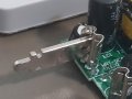
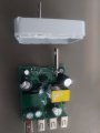
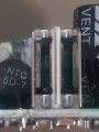
In tearing apart a 40W USB charger, I discovered these unusual (to me) receptacles used to make electrical connection between the AC mains blade pins that plug into the wall and the PCB. The first attached image is top-down, showing one of the blades poking out of the PCB receptacle. The second is looking directly into the PCB receptacle. I tried Google image search and various Digikey and Mouser searches, but haven't yet been able to find anything like it. So, 2 questions for the forum:
1. Do you know what this receptacle connector is called?
2. Why does it have 2 slots for the blade to slide into? I have a hard time believing the assembly tolerance is so bad that they need 4-8 millimeters of variation.
Thanks,
Dale
Attachments
-
 1.4 MB Views: 17
 -
 907.5 KB Views: 17