Can you connect PSU in series.

JohnSan

Joined Sep 15, 2018
130
It is acceptable and a common practice to connect DC power supplies in series, as long as they are isolated and there is a diode across each of the supply output terminals.

The diode is significant in when power is first applied to the power supplies. When they first start up, one will be quicker than the other. Depending on the load connected to them, the first up would appear as the full reverse voltage across the input of the last one up.
Not good news for the slow one!!
 
What seems confusing here is the different terms used to imply ISOLATED! Quite a few power supply circuits do not have the input side directly connected to the output side, either positive or negative, but the outputs are still not isolated from the input circuit. At least not completely isolated. THAT means that they can not be connected with the outputs in series.
So the bad news is that the determination about isolation is not always simple.

The GOOD NEWS is that there also are power supply circuits that can provide both positive and negative outputs of different voltages, all with a single common connection.

Actual isolation between the mains power in and the DC power out in a DC power supply demands a transformer at some point between the mains inlet connection and the DC output connection. The simple scheme for doing that often involves some sort of "inverter" circuit that includes a transformer operating at a much higher frequency, which allows the transformer to be both physically much smaller and also much less expensive.
 

Thread Starter

robp1956

Joined Jun 12, 2026
108
What seems confusing here is the different terms used to imply ISOLATED! Quite a few power supply circuits do not have the input side directly connected to the output side, either positive or negative, but the outputs are still not isolated from the input circuit. At least not completely isolated. THAT means that they can not be connected with the outputs in series.
So the bad news is that the determination about isolation is not always simple.

The GOOD NEWS is that there also are power supply circuits that can provide both positive and negative outputs of different voltages, all with a single common connection.

Actual isolation between the mains power in and the DC power out in a DC power supply demands a transformer at some point between the mains inlet connection and the DC output connection. The simple scheme for doing that often involves some sort of "inverter" circuit that includes a transformer operating at a much higher frequency, which allows the transformer to be both physically much smaller and also much less expensive.
After all that I have been told I came to the conclusion that I would not risk any of my power supplies for this. I have decided that the only way I will get what I need is to build my own power supply. with dedicated + and - supplies. I have started the Bom for that project. They just simply don't make a power supply that has what I want. or if they are available then they are way out of my price range.
 

Danko

Joined Nov 22, 2017
2,199
After all that I have been told I came to the conclusion that I would not risk any of my power supplies for this. I have decided that the only way I will get what I need is to build my own power supply. with dedicated + and - supplies. I have started the Bom for that project. They just simply don't make a power supply that has what I want. or if they are available then they are way out of my price range.
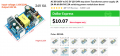
Connect outputs of these modules in any series combination as you like:
https://www.aliexpress.com/ssr/3000...1MzMwNDgkbzEkZzEkdDE3ODM1MzUxMzQkajI5JGwwJGgw
1783535567835.png
 

Thread Starter

robp1956

Joined Jun 12, 2026
108
But not 0 to -24 and that is what I want in one single power supply. I could use buck and boost converters but the boost ones are not that efficient at lower power. one switching power supply that is 24-0-24 output assuring me at least 20-0-20 outputs I have found the power supply just need to build from that. I looked into an equivalent transformer but the overall cost would increase by quite a bit. so switching seems to be my best bet.
 
Can you expand on this?
Probably: If the output is simply a DC regulated lower voltage than the input, I would not call it a power supply, but instead, it is a REGULATOR, for the reason that it does not have an AC input.
I define a "standard POWER SUPPLY" as a circuit that has an AC power input, most often a mains voltage, and a DC output voltage. THAT standard power supply MAY include a regulator circuit, but certainly a power supply does not have to be regulated, to be a power supply. If the circuit has a DC input and a DC output, it is probably a regulator. The exception would be a circuit with a greater voltage out than the input.

Mostly, regulators drop the positive input voltage relative to the negative input voltage level. BUT there certainly are NEGATIVE voltage regulators as well, with the common line between the input DC voltage and the output DC voltage being the positive side.
 

Danko

Joined Nov 22, 2017
2,199
But not 0 to -24 and that is what I want in one single power supply. I could use buck and boost converters but the boost ones are not that efficient at lower power. one switching power supply that is 24-0-24 output assuring me at least 20-0-20 outputs I have found the power supply just need to build from that. I looked into an equivalent transformer but the overall cost would increase by quite a bit. so switching seems to be my best bet.
Use this switching module with module from post #25.
1783545168897.png
Model nameDC 5A High Current Buck power supply module
Module propertiesNon-isolated Buck
Rectification modeNon synchronous rectifier
Input voltage5v-32v
Output voltage0.8v-24v
Output currentPeak 5A (3.5A above work to enhance heat dissipation)
Conversion efficiencyUp to 90%
Switch frequency300KHz
Output Ripple30mV (no-load)
Load Adjustment Rate± 0.5%
Voltage Adjustment Rate± 2.5%
Working temperature-40 to +85 .
Peripheral dimensions43*21*14 (long * wide * high) (mm)
 

Thread Starter

robp1956

Joined Jun 12, 2026
108
Power modules from posts #25 are 0 to +24 V, when 0 is grounded,
and are 0 to -24 V, when +24 V is grounded.
Still buck converters. What I want is variable 0-20V and 0 to 5 Amps on both the + and - sides. I'm not going to build a power supply that requires several buck converters for the job. rather just start from the switching supply output and make each of the power supplies. but that is the requirement I have so far.
 

Thread Starter

robp1956

Joined Jun 12, 2026
108
Probably: If the output is simply a DC regulated lower voltage than the input, I would not call it a power supply, but instead, it is a REGULATOR, for the reason that it does not have an AC input.
I define a "standard POWER SUPPLY" as a circuit that has an AC power input, most often a mains voltage, and a DC output voltage. THAT standard power supply MAY include a regulator circuit, but certainly a power supply does not have to be regulated, to be a power supply. If the circuit has a DC input and a DC output, it is probably a regulator. The exception would be a circuit with a greater voltage out than the input.

Mostly, regulators drop the positive input voltage relative to the negative input voltage level. BUT there certainly are NEGATIVE voltage regulators as well, with the common line between the input DC voltage and the output DC voltage being the positive side.
something like the switching supply I have picked. 110V 220V input and 24-0-24 DC output.
 
What my question was about was to connect 2 power supplies like you would 2 batteries to provide + and - supplies. I was considering building an analog posative and negative 28V supplies with a 12V 1A PS as a third output. I was looking at in the end a + and _ 24V variable 0.to 5 amp max output. I even have the transformer picked out just need to order it. 120/230V input and the outputs I mentioned 320W was what I was looking at and I thought with 2 channels flat out that would be about 240W for both and the 12V only adds 12W more or maybe 24W more to it if I get a 12V 2A out. I figured 320W should do it. But if I could for now take 2 of my PSU units I have and connect them like batteries that would work for now. but I have been told that this is a good way to destroy a PSU and I don't have a lot to go around. Not going to do dumb things like that. Also I have been looking into what sort of components I would need and Thinking that even if I can build it it is going to cost a lot of money to do it. it would have all I want in a 1 ton PSU but I will never have to move it. It's the beauty of being old. :)
Many linear bench supplies and some switching supplies have isolated outputs, so you can wire them like batteries:
PSU1: +24 V to your positive rail. Connect PSU1 negative to PSU2 positive. This becomes the 0 V reference. PSU2 negative becomes the -24 V rail. However, if either supply has its negative output tied internally to earth ground, putting them in series can short one supply through earth and potentially damage it.
 

Thread Starter

robp1956

Joined Jun 12, 2026
108
Many linear bench supplies and some switching supplies have isolated outputs, so you can wire them like batteries:
PSU1: +24 V to your positive rail. Connect PSU1 negative to PSU2 positive. This becomes the 0 V reference. PSU2 negative becomes the -24 V rail. However, if either supply has its negative output tied internally to earth ground, putting them in series can short one supply through earth and potentially damage it.
I'm really not into destructive testing any more especially when it comes to my equipment.
 

Thread Starter

robp1956

Joined Jun 12, 2026
108
Independently adjustable or tracking?

ak
I believe that that sort of thing can be manually controlled through a digital brain. everything will be mostly independent but the option of tracking should be there. I plan on being very picky with what I want it to do. I intend on this being the power supply that fulfills all of my wildest dreams. Gee if only this power supply had this, type of dreams. So corner cutting will be non existent and everything remains as cool as I can reasonably achieve.
 
IF the requester is able to examine the schematic diagram of a power supply, then a determinsation of isolation without any testing is possible.
AND, there is also a simple scheme using an ordinary multimeter, to verify the supply isolation or lack of isolation!
The first step is to decide which power supply connections would be actually connected in the desired series arrangement. The second step is then to switch on the power supplies that would be involved in the series connection, and adjust those supply outputs to the intended voltage. Then the third step is to use the multimeter to measure for any voltage between the terminals that would be connected in the series arrangement. Start with a higher voltage range setting of the meter, and make both AC voltage and DC voltage measurements.
IF, and only IF, a zero voltage is measuredbetween those terminals, then a series connection tying those terminals together will be safe.
This scheme can be used for any number of power supplies to be connected in series.
 
Top