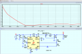
Can someone help me get this part to simulate in lt-Spice

Thread Starter

mike _Jacobs

Joined Jun 9, 2021
223
As requested. Please post your asc file, so that we can all sing from the same hymn-sheet.
This is the file with it not working.

If you give D1 and C2 seperate grounds , it works.

Take a look a post up where i posted the working and none working version with the arrows pointing to the ground connection showing it not working in one and then working in another
 

Attachments

ericgibbs

Joined Jan 29, 2010
21,531
hi mike,
The way you have drawn the wire link from the diode to the capacitor it is not connected at the C2 point
Also, you need the K1 L1 L2 1 on the circuit.

I don't have your Schottky diode, it is an equivalent.

Try this asc file
E
EG57_ 1102.png
 

Attachments

ericgibbs

Joined Jan 29, 2010
21,531
hi mike,
The two inductors are mutually coupled when using K1 L1 L2 1
The '1' indicates the coupling is 100%, or say 0.5 =50%.

Its in the LTS Help files

Did mjy asc file work OK?

E
 

Thread Starter

mike _Jacobs

Joined Jun 9, 2021
223
hi mike,
The two inductors are mutually coupled when using K1 L1 L2 1
The '1' indicates the coupling is 100%, or say 0.5 =50%.

Its in the LTS Help files

Did mjy asc file work OK?

E
Thanks, mine works but yours works better.

I dont understand the mututal inductance thing. These are two inductors in series. If you go buy the recommended part from digi key from the data sheet its

DRQ74-330
https://www.digikey.com/en/products...7312?s=N4IgTCBcDaIAQBEBKBFA7AFgLQGYcAYQBdAXyA

This is not a transformer its two inductors. So why am i specifying mutual inductance in the sim?
 

Thread Starter

mike _Jacobs

Joined Jun 9, 2021
223
Thanks, mine works but yours works better.

I dont understand the mututal inductance thing. These are two inductors in series. If you go buy the recommended part from digi key from the data sheet its

DRQ74-330
https://www.digikey.com/en/products...7312?s=N4IgTCBcDaIAQBEBKBFA7AFgLQGYcAYQBdAXyA

This is not a transformer its two inductors. So why am i specifying mutual inductance in the sim?
ok guess i screwed up
Looking at that part again, it is a little transformer
So this is what makes it a flyback, the isolation.

Is there a way to negate the isolation if you dont need it?
Or could you help me pick an easier part to deal with?
I dont need flyback but i need a little converter like this that i can generate -12V from
 

crutschow

Joined Mar 14, 2008
38,674
They don't specify the mutual coupling between the two windings, but it is likely very similar to a standard transformers of that size.
 

Thread Starter

mike _Jacobs

Joined Jun 9, 2021
223
hi,
The Voltage Input and Outputs are not isolated.
What is your design requirement.?
E
I dont have a design isolation requirement. I just need something that will generate a -12V rail with as little as 5V input.
~50mA current at -12V
But i dont want to get into flybacks and magnetics if i can help it.
 

Ian0

Joined Aug 7, 2020
13,227
The circuit shown is a Čuk converter. It will work with two separate inductors or with coupled inductors. It works best with inductors that are badly coupled, such as two windings each occupying 180° of a toroid, with K about 0.9
 
Top