Can someone explain me the working of this circuit?? Squarewave Oscillator

Thread Starter

Mayank_2606

Joined Jun 10, 2020
57
I am new to LTSPICE and have been experimenting with designing with op amps as filters and oscillators
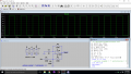
I recently came around this circuit of a "squarewave oscillator" in LMx58 Datasheet and with an aim to replicate it i decided to use an op amp in the LTSPICE viz. LT1007 to create a similar circuit to produce a square wave.

but i am not able to narrow down the expression for Vout in it and also what the effect of changing Vin would be on the circuit.
Can someone please help me at this?

Thank you
 

Attachments

Irving

Joined Jan 30, 2016
3,878
Assume C1 discharged and Vout is +ve, then C1 charges through R4 until -input of opamp > +input voltage set as % of Vout (R2 & R3 offset by Vin through R1). Then Vout goes -ve discharging C1 through R4, and reducing +input voltage to a low level. When C1 discharged to that low level cycle repeats.

Use KCL to determine voltage at +input of op amp when Vout = +15 and Vout = -15, and across range of Vin values to see switching points of capacitor volts.
 
Last edited:

Thread Starter

Mayank_2606

Joined Jun 10, 2020
57
I used KCL to determine node voltages at V+ and V-

And obtained either as :
R1=R2=R3=R4=R

V+ = (Vin+Vout)/3
And
V- = (Vout*Xc)/R

After than I took Vout as Aol*(V+ - V-)
Is this a right approach??
Also can I use Virtual ground concept here ?
 

Irving

Joined Jan 30, 2016
3,878
Not quite. By using Xc you are trying an AC small signal analysis approach when really this is a DC problem.

Lets assume ideal opamp, so outputs are VoH = +15v and VoL = -15v (From the waveform we can see that VoH is +14v and VoL is -14v, but we'll stick with +/-15 for now).

Assume Vin is 0v and opamp is generating VoH. Then opamp +input is VoH . (R1//R3) / (R2 + R1//R3) where // means 'in parallel with'. By inspection R1//R3 = 50k and so +input is 15 . 50/(100+50) = 5v. Similarly, when output is VoL the +input is -5v.

Assume voltage on capacitor is 0v and opamp output has just gone to VoH. Capacitor C1 charges via R4. When it gets to 5v, the opamp -input becomes > its +input and the output swings to VoL. The voltage on the capacitor is given by V = Vo . (1 - e ^ (-t/R4.C1)) or, solving for t, t = -R . C . ln(1 - V/Vo). t at time when V = 5v is = -1e5 . 1e-6 . ln(1 - .333) = 40.5mS

Now opamp output swings to VoL = -15v and +input is -5v. Capacitor now discharges from +5v to -5v, a -10v swing in time t = -1e5 . 1e-6 . ln(1-(-10)/(-15)) = 0.110s , the opamp out swings to VoH and the cycle repeats ad infinitum...

Now use KCL/KVL to assess impact of Vin on the opamp +input voltage when opamp output is either VoH or VoL. I'll leave that as an exercise for you, but before doing any math can you suggest by inspection and knowing now how the circuit works what impact it might have?

As a second 'non-math' answer, what happens if I change the supply volts to +/-10v? and again, +15/-10v?
 
Last edited:

Thread Starter

Mayank_2606

Joined Jun 10, 2020
57
Hey Irving.

Thank you so much for this thorough explanation for this circuit.

For the questions you asked,

Changing Vin would directly impact the ON time and the OFF time for the Square wave. As Vin is directly responsible for the voltage at +input of opamp and here the time taken for the capacitor to charge would follow the trend such as it would charge till the potential across it is about the same as +input voltage for Vout bring VoH and VoL either and hence would directly impact the time for which the opamp maintains VoH and VoL.


And I believe changing the dual supply voltages would also impact the on and off time for the Square wave. Considering same conditions such as Vin = 0 :
1) For supply being, ±10V, +input voltage would be less than the one in case of +/-15v. Hence would change both the on and off time for the output at VoH and VoL.

2) For supply being +15/-10, for similar Vin. The on time should not be affected and should be same as the original conditions while the off time would be affected.

For the exact values of how much on and off times for VoH and VoL would be after changing supply, I will calculate them for sure. And also find the direct impact of Vin on Vout.

Thank you again for taking time writing the explanation.
 

Irving

Joined Jan 30, 2016
3,878
You're welcome.

I made a small mistake in my explanation in post #4. After the first charge cycle where Vc goes from 0 to +5v, the capacitor discharges (or charges negatively) from +5v to -5v. But whereas on the first cycle the driving voltage is VoH, on the second and subsequent periods the driving voltage is the opamp output + the voltage on the capacitor, i.e. when the output goes to VoL = -15v, the capacitor is already at +5v so the driving voltage is 20v. Therefore the time taken is actually

t = -1e5 . 1e-6 . ln(1-(-10)/(-20)) = 0.069s

Effect of Vin
You are correct, Vin controls the duty cycle, the ratio of on- to off-time. A +ve value at Vin increases on-time, a -ve value decreases it.

Effect of Changing supply voltages
1) Changing both supply voltages should not change the on/off times. Why? The test for switch over is determined by the voltage on opamp +input, which is a % of Vo set by R1 - R3. Now consider the capacitor charging formula; the time t is dependent on the ratio of Vc to Vo. But Vs, the value of Vc at switchover is also equal to that % of Vo, so t is only dependent on the %; the Vo absolute value is of no consequence.

i.e. the frequency of oscillation is only dependent on the R4 . C1 time constant and the ratio 'r' set by R1, R2, R3, as long as |VoH| = |VoL|.

2) If VoH and VoL are different then there is an impact on both on- and off- periods. When Vo switches from VoH to VoL the capacitor has to discharge (or negatively charge) from +%VoH to 0v and then down to a -%VoL, both relative to VoL. Similarly, in the opposite direction from a -%VoL up to a %VoH, relative to VoH. So a reduced VoL, compared to VoH will reduce the on time and increase the off time.

Proving 1 & 2
We can write the following equations (using the identity -ln(x) = ln(1/x)):

t(on) = R . C . ln(1/(1 - r . (|VoH| + |VoL|)/(|VoH| + r . |VoL|)))
t(off) = R . C . ln(1/(1 - r . (|VoH| + |VoL|)/(|VoL| + r . |VoH|)))

where r is defined as above.

If |VoL| = |VoH| then

t(on) = t(off) = R . C . ln(1/(1 - .333 . (2|VoH|)/(1.333|VoH|)) = 0.69 . R . C

If |VoL| = 0.666|VoH| then

t(on) = R . C . ln(1/(1- .333 . (1.666/1.666))) = 0405. R . C
t(off) = R . C . ln(1/(1 - .333 . (1.666/1))) = 0.81 R . C

You will see that the theoretical values of t(on) and t(off), 0.069S, when |VoH| = |VoL|, are not that close to the simulation at 0.063S. This is because the emulation of the op amp is a long way from being an ideal op amp, with zero offset voltage and zero input bias current. Indeed its quite some way off being accurate for the OP07 part its supposedly modelling.
 
Last edited:

Thread Starter

Mayank_2606

Joined Jun 10, 2020
57
Why? The test for switch over is determined by the voltage on opamp +input, which is a % of Vo set by R1 - R3. Now consider the capacitor charging formula; the time t is dependent on the ratio of Vc to Vo. But Vs, the value of Vc at switchover is also equal to that % of Vo, so t is only dependent on the %; the Vo absolute value is of no consequence.
I tried that with different values and yeah that seem to work. I don't know why i am surprised at this discovery.
Also thank you for adding in that part about the capacitor's voltage changing from +5 to -5 would occur with a voltage of VoL + the voltage at capacitor at that time.

You will see that the theoretical values of t(on) and t(off), 0.069S, when |VoH| = |VoL|, are not that close to the simulation at 0.063S. This is because the emulation of the op amp is a long way from being an ideal op amp, with zero offset voltage and zero input bias current. Indeed its quite some way off being accurate for the OP07 part its supposedly modelling.
Yes i was wondering why the actual values differ quite a way off. But I think now I have the gist of the whole situation.

Once again thank you for taking time to write this.

I am a sophomore pursuing to be a Electronics and Telecommunication engineer. I want to become an Analog Design Engineer in the future and always am wondering as to what path should i follow. Can i give me some tips as to how should i tackle the basics and how to continue ahead.
 

Irving

Joined Jan 30, 2016
3,878
Hi,

Sophomore, that's 2nd year high school, so 15-16y old, I think? I'm in UK, so the term isn't familiar to me. I guess you'll be looking to go on to study for a degree at Uni in a couple of years, in electronics - there are many options. University isn't the only route though (well here in UK you can do an apprenticeship which combines paid practical work with theoretical learning).

Well, if electronics is truly your interest, I wouldn't focus too much right now on a particular branch. Get a good grounding in the basics; the why & how of components and the physics & 'laws' (Kirchhoff, Ohm, Lenz, Faraday, etc., etc.) that underpin them, a good/deep understanding of the basic building blocks of electronics - amplifiers, oscillators, filters, tuned circuits, modulators/demodulators, and so on, and concepts such as gain, phase shift, noise & signal-to-noise ratio, resonance, impedance matching, and so on, that control how these blocks work and interact together, and how to read a data sheet to assess the suitability of a component. These are what makes a good design engineer. I know your current thinking is analogue, but don't forget the digital side of things - much, arguably, most, of the systems used today are digital internally, and only analogue at the periphery.

But alongside the theoretical understanding, and IMHO, arguably more important, are the practical skills of how to physically build systems, assess the impact of, & design for, component tolerances, temperature drift, power dissipation/losses, how the physical layout impacts and effects the operation of the circuit and how to lay out a PCB. How to measure, test, and fault-find what you've built (and equally how to evaluate what someone else has built) and the tools and techniques for doing so (learn how to properly use and interpret readings on a multimeter, oscilloscope, spectrum analyser, etc.).

Simulators, like Spice and other programs, are great (though a relatively recent option), but there's nothing like building real stuff to bring home all of the above. You'll learn a lot, though not all, of that at Uni, but doing it yourself, applying it to real projects, is where it gets concreted. Have you designed/built anything yourself? Do you have a hobby bench setup at home? Learn how to solder, wire things up.

For me, electronics was a hobby - I built my first radio at age 7 - long before it was a career spanning the last 55 years and still going strong - I'm still learning stuff even now.

There's a huge amount of learning material online, on YouTube, or through organisations such as SkillShare, Brilliant, etc. If you want a book, the bible is 'The Art of Electronics' by Horowitz & Hill. Get someone to buy it for you for your birthday, you won't regret it.
 
Last edited:

Thread Starter

Mayank_2606

Joined Jun 10, 2020
57
Sophomore, that's 2nd year high school, so 15-16y old, I think? I'm in UK, so the term isn't familiar to me.
I actually am in University, I am currently pursuing Bachelor's in Electronics and Telecommunication and am in second year, We have Bachelor's of Engineering which is for 4 years. I started really late I know. I didn't had much exposure to electronics in my country. I live in India, and when i started electronics it was mostly due to playing around with components and quite basic stuff, like LED blinking, 555 timers etc. I know not much impressive but that's how it was. It was in my 10th grade, which should be 1st year High School i think, we follow a different system, When i got into IoT and started playing around with Arduino and Rpi. I made a few projects then, like a line follower, a distance based braking system for a competition and other few projects that helped me grasp the basics of those boards, especially Arduino.

Then later at my first year of university, I realized how much shallow my knowledge is and wanted to become better at core electronics but wasn't sure how to go about it. I have been learning about the many things yet again like diodes, transistors, etc.

I also realize I am way behind the curve but I want to become better at it. This is something i really feel passionate about and want to know the working and hows and when and whats of it and eventually design my own.

I will implement all of your suggestions as a way of learning. And yeah i have also been studying Digital Design. I am taking a course on Coursera currently about FPGA design and am learning VHDL through that. Other than that i have been simulating digital circuits on Logisim and CEDAR. I am still far from perfect at it but i believe I will reach there.

For me, electronics was a hobby - I built my first radio at age 7 - long before it was a career spanning the last 55 years and still going strong - I'm still learning stuff even now.
That's really amazing! Like 55 years, that's really a inspiring milestone. Maybe I will build one too and a few more things as I learn and experiment more. I am being taught soldering at University and also doing some by myself. I don't have a Hobby bench yet. Can't afford it as a broke college student XD. My projects won't sound as impressive but i have made a few, like PWM using 555 timer, Rain sensing wiping system, A few using arduino etc.

Your reply have really given me quite a direction, as i have been in shambles and picking up anything and everything at once right now. Thanks.
I hope to learn and grow with this. And I will be bothering you for the time being at AAC, hope you don't mind.

Have a great day Sir.
Thank you again.
 

Irving

Joined Jan 30, 2016
3,878
My apologies... I thought you were in the US!

Sounds like you're doing ok to me, better than some students I know. Get the basics under your belt, the rest will follow.

Feel free to ask questions, but do it through the private messaging system.
 

crutschow

Joined Mar 14, 2008
34,408
I was an analog design engineer for most of my 44 year career.
I always found analog more interesting than digital, although I learned enough digital to design simple digital circuits.
Never got past much past Basic though, in computer programming. C is way too cryptic for my tastes.

Spice is very useful in exploring analog circuit operation and design, and detecting circuit errors before the circuit is built.
One advantage, compared to real circuits, is being able to look at currents and voltages anywhere in the circuit without disturbing the circuit operation.
I started using Spice when the circuit had to be submitted on IBM cards for main-frame processing, and have used it ever since to do circuit design and also look for circuit operational problems in circuits already built.
But of course, for any real design, you need to breadboard the circuit to verify its operation before you commit to the design.
 

sparky 1

Joined Nov 3, 2018
756
A video showing how to check a test question answer using LTspice .
There is also an explanation for the direction of current using LTspice.

I simulated a virtual ground that uses two 9V batteries for low cost.
It is nice to have a reference circuits handy that can be modified.
virtual ground.JPG :
 
Last edited:

Thread Starter

Mayank_2606

Joined Jun 10, 2020
57
Thank you for sharing your experience with me. I hope I will learn enough as i go on this journey of electronics to be able to relate to these processes involved and get better with the AAC community.

But of course, for any real design, you need to breadboard the circuit to verify its operation before you commit to the design.
Yes, I will make sure to follow this.

Also thanks for sharing your circuit collection with me, It will sure help me a lot when designing my own.
 

Thread Starter

Mayank_2606

Joined Jun 10, 2020
57
A video showing how to check a test question answer using LTspice .
There is also an explanation for the direction of current using LTspice.

I simulated a virtual ground that uses two 9V batteries for low cost.
It is nice to have a reference circuits handy that can be modified.
View attachment 209925 :
Thank you for sharing that video clip with me.
I will make sure to follow up on that.

Also about the reference circuit.
I think i will try to solve it on my own now with a few variations to really get a hold of it.
 

sparky 1

Joined Nov 3, 2018
756
Interesting, but what do you see as the benefit (and negatives) of that over just taking a ground from the junction of the two batteries?
Good question. The circuit can use any number of batteries in series. An example could be just one battery, or a power supply. Starting with a formal layout just reminds of how it goes. It can always be simplified or regulated. The virtual ground should be quick and easy to set up. Sometimes just a review not an absolute but an approximation that needs to be tuned using a multimeter.
 
Last edited:
Top