Can someone correct my view of resonance.

Thread Starter

Xenon02

Joined Feb 24, 2021
504
Neither of the circuits you circled is a single L and C in series or parallel, so what you know about those cases does not apply, yet you insist on doing so. In your other thread, it took forever for you to understand that Ohm’s law does not apply to caoacitors. I am not interested in going through that tedious process again, hence the never mind.
So you say that in orange circle isn't a series resonance ?

So how does it work then. I'll try to apply your suggestion. It's true that I used L and C series and parallel example (simple RLC circuit) in here. Some users here says that it works somehow like that in advanced circuit. So I've decided that maybe to determine the resonance I should use the equation for total value of Z or Y. Like in the post #15. If there is a resonance then this Z should be equal 0. And only R is in the circuit. So looking at those 2 frequences that shows max/min I thought that maybe the min here shows that L and C elements acts like short circuit. But the thing is that 35 Hz is for one branch. Which reduces the imaginary value only of this one branch. The other branch isn't in resonance so the equation for total value isn't correct and this shouldn't be the resonance because the total value of imaginary value isn't equal 0.
 

Thread Starter

Xenon02

Joined Feb 24, 2021
504
Do you see a single L in series with a single C in the orange circle?
In orange circle ? No
But in parallel yes ? So what is this resonance in this branch ? What does it mean that it is in resonance ? And the other branch is not.
 
Last edited:

Thread Starter

Xenon02

Joined Feb 24, 2021
504
Because I don't know how to interpret the resonance I have in charts. And the knowledge I have. When is the resonance for you ? Is it when total value of imaginary value is equal 0 or what exactly ?
 

WBahn

Joined Mar 31, 2012
33,234
You need to learn to analyze the circuits, not just try to throw hand-wavy concepts at them.

\(
Z_L \, = \, j \omega L \\
Z_C \, = \, \frac{1}{j \omega C} \, = \, -j\frac{1}{\omega C}
\)

So you can already see that saying ZL = ZC is problematic because the first is a positive imaginary value and the second is a negative one, so the only way that they can ever be equal is if both are identically zero. But that's not what is required for resonance.

Once you can convert capacitances and inductances to impedances, you can now combine them algebraically just like resistors in DC circuits.

For your circuit, you have three reactive segments that are in parallel. I'll call them:

Z_A consists of C1, L1, and L2
Z_B consists of L3
Z_C consists of C2, L4, and L5

The total impedance of the reactive portion (and just the reactive portion, the sole resistor is in parallel separately) is thus

Z = Z_A || Z_B || Z_C

You can find these by noting that

Z_A = (Z_C1 || Z_L1) + Z_L2
Z_B = Z_L3
Z_C = (Z_C2 || Z_L4) + Z_L5

Now it's plug and chug time. You can either do this symbolically, which will reveal the most potential understanding of what is going on, but will likely require some head scratching, or you could use a spreadsheet to generate plots of the reactances of each of the three branches as well as the overall reactance as a function of frequency.
 

Thread Starter

Xenon02

Joined Feb 24, 2021
504
You need to learn to analyze the circuits, not just try to throw hand-wavy concepts at them.

\(
Z_L \, = \, j \omega L \\
Z_C \, = \, \frac{1}{j \omega C} \, = \, -j\frac{1}{\omega C}
\)

So you can already see that saying ZL = ZC is problematic because the first is a positive imaginary value and the second is a negative one, so the only way that they can ever be equal is if both are identically zero. But that's not what is required for resonance.

Once you can convert capacitances and inductances to impedances, you can now combine them algebraically just like resistors in DC circuits.

For your circuit, you have three reactive segments that are in parallel. I'll call them:

Z_A consists of C1, L1, and L2
Z_B consists of L3
Z_C consists of C2, L4, and L5

The total impedance of the reactive portion (and just the reactive portion, the sole resistor is in parallel separately) is thus

Z = Z_A || Z_B || Z_C

You can find these by noting that

Z_A = (Z_C1 || Z_L1) + Z_L2
Z_B = Z_L3
Z_C = (Z_C2 || Z_L4) + Z_L5

Now it's plug and chug time. You can either do this symbolically, which will reveal the most potential understanding of what is going on, but will likely require some head scratching, or you could use a spreadsheet to generate plots of the reactances of each of the three branches as well as the overall reactance as a function of frequency.
Okey so what is required to have resonance ? I know that there is something like maximum and minimum. What is the difference ?

Also if I calculate the total Z. I have to also add resistor right ?
Z + R = Z_total.
And from this Z_total I take Imaginary value Im{Z_total}. And what then ?

Also in the previous posts they said that one branch out of 2 is in resonance but shouldn't all be in resonance so all imaginary value is equal 0 ?
 

WBahn

Joined Mar 31, 2012
33,234
Okey so what is required to have resonance ? I know that there is something like maximum and minimum. What is the difference ?

Also if I calculate the total Z. I have to also add resistor right ?
Z + R = Z_total.
And from this Z_total I take Imaginary value Im{Z_total}. And what then ?

Also in the previous posts they said that one branch out of 2 is in resonance but shouldn't all be in resonance so all imaginary value is equal 0 ?
"Resonance" is one of those somewhat squishy terms whose meaning depends on what the focus of the current context is.

In AC circuits, it is generally related to the condition where reactive energy is being locally stored within some portion of a system. To the rest of the circuit, the often results in that portion of the circuit looking purely resistive. In practical terms, circuits seldom hit this ideal case, and so resonance often refers to frequencies were the response has a relatively sharp local minimum or maximum.

If you have a circuit with multiple branches, there is no reason to assume that all branches will be in resonance at the same time -- you can change one branch without changing the others, so how could such a thing be imposed?

In anything other than the simplest series or parallel circuits, the frequency response gets very complicated. As one part's reactance is increasing another part's may be decreasing at a different rate and at some point they cancel out resulting in a resonance effect even though neither portion itself is anywhere near its individual resonance point.

In looking at your simulation result, it's a bit hard to tell what is what. You are plotting the voltage on node n001, but there's no indication which node that is. I'm going to assume it's your top node. Then, the plot is in dB, but that means there has to be a reference level. I'm going to guess that your simulator is using a reference level of 1 V for it's dB calculations. Your signal source has an amplitude of 1 A (I don't know if that's RMS or peak, but as long as everything is interpreted the same way, it largely doesn't matter for this discussion). So what would the voltage be if the circuit ONLY had the 1 kΩ resistor? It would be 1000 V, which when converted to dB the way the simulator is doing it would be 60 dB. That's consistent with where your two spikes peak out at and where the response appears to be headed at the frequency gets arbitrarily large.

Speaking of which, what DO we expect the response to be for very high or very low frequencies?

At very low frequencies, the two capacitors will look like open circuits leaving us with three inductors in parallel, all of which will look like short circuits, so the voltage across the resistor should be very close to zero. But what about at 1 Hz, the lowest frequency in your plot? Assuming that this is still low enough for the capacitors to look like open circuits, that means that each 400 mH inductor will have a reactance of about 2.5 Ω, yielding a total reactance of about 1.25 Ω. This is so much smaller than the resistor that the overall circuit will look like a 1.25 Ω reactance and have a voltage of about 1.25 V, which would be plotted as about 2 dB. That jives with your plot.

At very high frequencies, the capacitors will look like short circuits, but the inductors in each branch will look like opens and thus the overall circuit will look like just the 1 kΩ resistor, yielding a voltage plotted at 60 dB,

What about at 1 kHz, the upper limit of your plot? Let's assume that this is high enough for the two capacitors to look like short circuits (at least relative to the inductors). This assumption seems pretty reasonable given the two spikes in the 30 Hz and 50 Hz regions, which likely represent where the capacitors are "crossing over" the inductor reactances in their respective branches. So that means that we now have three 400 mH inductors in parallel, each of which has about 2.5 kΩ of reactance, yielding around 800 Ω total. This, in parallel with the 1000 Ω resistance would have an impedance of about 625 Ω, which would translate to the voltage being plotted at about 56 dB. This is in excellent agreement with your plot.

So what remains it to gain a better understanding of what is happening at the two peaks and the two valleys. For that, you want to delve into what is happening in each of the three parallel branches and how they each contribute to the total reactance of the circuit near those frequencies.

EDIT: Corrected units typo on current source amplitude pointed out by Jony130.
 
Last edited:

Thread Starter

Xenon02

Joined Feb 24, 2021
504
In AC circuits, it is generally related to the condition where reactive energy is being locally stored within some portion of a system. To the rest of the circuit, the often results in that portion of the circuit looking purely resistive. In practical terms, circuits seldom hit this ideal case, and so resonance often refers to frequencies were the response has a relatively sharp local minimum or maximum.
Okey I believe that I undestand this part.
I mean I understand the first part in which the circuit is looking like it's purely resistive. But maximum and minimum but of what ? Total impedance with imaginary part ?


If you have a circuit with multiple branches, there is no reason to assume that all branches will be in resonance at the same time -- you can change one branch without changing the others, so how could such a thing be imposed?
And that's why I was concerned.
I can imagine that one of those branches are in resonance and the other is not. It's more like is it mathematically possible.
Because when there is one spike which is 35 Hz. Then this is a local minimum. So What will happen ? Will it act like a series resonance or like a parallel resonance ? Of course I should look at simple RLC but isn't this the meaning behind Min and Max ? That they act like series resonance or parallel resonance ?

And why did I say mathematically. Because I read a lot about calculating resonance (most of them are simple RLC). And they said that I have to take imaginary part of impedance or admittance. Something like Z_total = R + jZ to Im{Z} = Z.

But I didn't know what to do about it. Because there said that for series resonance Im{Z} = 0 but Im{Y} = infinite. So yea here is a problem.

And why I was also concerned ? In the comments I read that this branch is in resonance and the other is not.
So mathematically the imaginary part should be zero for resonance right or infinite I don't know. But If one branch is in resonance then it's imaginary part is 0 but the other one is not 0 because it is not in resonance. So Is it like first branch eliminates imaginary part from second branch ? Se the imaginary part of Z_total is equal 0 like for resonance ?

EDIT:

Those calculations are related of how to find this resonance frequency.
 
Last edited:

WBahn

Joined Mar 31, 2012
33,234
Okey I believe that I undestand this part.
I mean I understand the first part in which the circuit is looking like it's purely resistive. But maximum and minimum but of what ? Total impedance with imaginary part ?
Depends on what is of interest. Look at your plot. It shows the voltage response of the circuit as a function of frequency and shows that there are two local maxima and two local minima. If you are interested in the voltage response of the circuit, those are the points that should be of particular interest (or concern). If you are not interested in the voltage response, then why plot it. Plot what you are interested in and consider where that response has maxima and minima.

And that's why I was concerned.
I can imagine that one of those branches are in resonance and the other is not. It's more like is it mathematically possible.
Because when there is one spike which is 35 Hz. Then this is a local minimum. So What will happen ? Will it act like a series resonance or like a parallel resonance ? Of course I should look at simple RLC but isn't this the meaning behind Min and Max ? That they act like series resonance or parallel resonance ?
Terms like "series resonance" and "parallel resonance" largely only have meaning when you are talking about a series circuit or a parallel circuit. Once you move to more complex topologies, those terms become largely meaningless without being VERY explicit about what YOU are trying to accomplish or communicate.

And why did I say mathematically. Because I read a lot about calculating resonance (most of them are simple RLC). And they said that I have to take imaginary part of impedance or admittance. Something like Z_total = R + jZ to Im{Z} = Z.
Z is traditionally the symbol for impedance, which is the combination of resistance (R) and reactance (X). So

Z = R + jX

The reactance of an impedance is X = Im{Z}

Reactance, X, is a real number that can be positive (inductive) or negative (capacitive).
Impedance, Z, is a complex number that has a resistive component, R = Re{Z}, and a reactive component, X = Im{Z}.

You ability to communicate your thoughts will improve if you try to use the standard notations (which is not always possible).

But I didn't know what to do about it. Because there said that for series resonance Im{Z} = 0 but Im{Y} = infinite. So yea here is a problem.
Again, you are trying to force concepts that apply to specific, simple circuits to larger, complex circuits.

And why I was also concerned ? In the comments I read that this branch is in resonance and the other is not.
So mathematically the imaginary part should be zero for resonance right or infinite I don't know. But If one branch is in resonance then it's imaginary part is 0 but the other one is not 0 because it is not in resonance. So Is it like first branch eliminates imaginary part from second branch ? Se the imaginary part of Z_total is equal 0 like for resonance ?
One branch might be in resonance such that, at that frequency, that branch looks like a resistor. That other branches look like the other branches.

If two branches are not in resonance at the same frequency, then if there is a resonant frequency for the overall circuit it will not occur at either of those frequencies. Instead, there will be some other frequency at which the interaction between the two branches makes the combination of the two branches look purely resistive. But that might not happen at all. The circuit response gets very complicated very quickly and the devil is very much in the specific details of that circuit.
 

Thread Starter

Xenon02

Joined Feb 24, 2021
504
Depends on what is of interest. Look at your plot. It shows the voltage response of the circuit as a function of frequency and shows that there are two local maxima and two local minima. If you are interested in the voltage response of the circuit, those are the points that should be of particular interest (or concern). If you are not interested in the voltage response, then why plot it. Plot what you are interested in and consider where that response has maxima and minima.
I've received this diagram from a friend of mine, so I don't really remember what was this plot.


Terms like "series resonance" and "parallel resonance" largely only have meaning when you are talking about a series circuit or a parallel circuit. Once you move to more complex topologies, those terms become largely meaningless without being VERY explicit about what YOU are trying to accomplish or communicate.
Ok so series resonance and parallel resonance for simple circuit such as RLC in most of (1 resistor, 1 capacitor, 1 inductor) simple ones. For larger it is different. But can you tell me why in the beggining they said that is acts like one of those terms ?


Again, you are trying to force concepts that apply to specific, simple circuits to larger, complex circuits.
Okey so it's not Im{Z} = 0. So how do I calculate the frequency that the circuit is in resonance ?

Because I can assume that those local Min/Max are the resonance that the whole circuit is on ?
Also I read that when the circuit is in resonance then current is in phase with voltage for voltage supply or current supply.

From the definition we want to have circuit that is seen as resistive. Voltage source/Current source if it sees the circuit as purely resistive then it is a resonance for the whole circuit in which current is in phase with voltage.


One branch might be in resonance such that, at that frequency, that branch looks like a resistor. That other branches look like the other branches.

If two branches are not in resonance at the same frequency, then if there is a resonant frequency for the overall circuit it will not occur at either of those frequencies. Instead, there will be some other frequency at which the interaction between the two branches makes the combination of the two branches look purely resistive. But that might not happen at all. The circuit response gets very complicated very quickly and the devil is very much in the specific details of that circuit.
So those peaks 2 min and 2 max, are the resonance for both branches ? That makes look at the circuit as purely resistive ?

But is it okey that only one branch is in resonance and the voltage source/current source sees the whole circuit as a purely resistive ? I mean it's not really logical for me, because I only know the basics. I thought that every reaktance has to be reduced ? So the only thing that occurs is purely resistive circuit.
 

WBahn

Joined Mar 31, 2012
33,234
Ok so series resonance and parallel resonance for simple circuit such as RLC in most of (1 resistor, 1 capacitor, 1 inductor) simple ones. For larger it is different. But can you tell me why in the beggining they said that is acts like one of those terms ?
In the beginning who said what? I'm not going to wade through dozens of posts trying to figure out which one you are referring to.

Okey so it's not Im{Z} = 0. So how do I calculate the frequency that the circuit is in resonance ?
In a complex circuit, the overall reactance may never go to zero (or infinity, as the case may be). You generally looking for local minima and maxima.

Because I can assume that those local Min/Max are the resonance that the whole circuit is on ?
Generally that is the case. But it's important that you are looking at the min/max of the thing you are interested in.

Also I read that when the circuit is in resonance then current is in phase with voltage for voltage supply or current supply.

From the definition we want to have circuit that is seen as resistive. Voltage source/Current source if it sees the circuit as purely resistive then it is a resonance for the whole circuit in which current is in phase with voltage.
IF the circuit, as seen by the supply, is purely resistive, then the supply current will be in phase with the supply voltage.

So those peaks 2 min and 2 max, are the resonance for both branches ? That makes look at the circuit as purely resistive ?
Not necessarily. They are points of minimum (or maximum) response. That does NOT mean zero (or infinite) response, it means that the response is bigger (or smaller) on both sides of that frequency.

But is it okey that only one branch is in resonance and the voltage source/current source sees the whole circuit as a purely resistive ? I mean it's not really logical for me, because I only know the basics. I thought that every reaktance has to be reduced ? So the only thing that occurs is purely resistive circuit.
If only one branch is in resonance such that THAT branch looks purely resistive, that does NOT mean that other branches, or the circuit as a whole, looks purely resistive.

If there is a point at which the overall circuit looks purely resistive, it will almost certainly be at a point at which none of the individual branches do. Instead, it will be at a point where all of the branches can mutually pass the reactive energy back and forth between them in such a way that the external source, once steady state is reached, no longer needs to source/sink it every cycle.
 

WBahn

Joined Mar 31, 2012
33,234
It is a current source. A one amp peak current source (1A peak). We in Poland use such a strange symbol for a current source. I don't like him either.
Typo on my part - thanks for catching it. Meant 1 A. All of the conversation was with the awareness that it's a 1 A current source (hence 1000 V across the resistor if the rest of the reactances can be made to look like an open).
 

Thread Starter

Xenon02

Joined Feb 24, 2021
504
In the beginning who said what? I'm not going to wade through dozens of posts trying to figure out which one you are referring to.
Here :


From the simulation results, we can see that at the parallel resonance we have an open circuit. Because Vout = 60dB = 1000V (1A * 1kΩ).
And at the series resonance, we have Vout = -7dB ≈ 0.447V. So, the resistance at series resonance is equal to Rs = 0.447V/1A = 0.447Ω.

At arond 35Hz it will be C2 L4||L5 and at 50Hz C1 L1||L2.
Also, don't forget that if we have two resistors connected in parallel the smallest one will "win" and dominate the whole circuit.
And this is why we have Rs = 0.447Ω ar series resonance.
Series and parallel resonance. It's mentioned here.


In a complex circuit, the overall reactance may never go to zero (or infinity, as the case may be). You generally looking for local minima and maxima.
If it's not zero then from those max/min they are telling me about reactance value ? That reactance can be close to 0 min or reactance can be close to infinite max (very high value)? Or is it about imaginary value Im {Z} min/max ??


IF the circuit, as seen by the supply, is purely resistive, then the supply current will be in phase with the supply voltage
Isn't it the purpose for resonans ?That the supply has current and voltage in phase.


Not necessarily. They are points of minimum (or maximum) response. That does NOT mean zero (or infinite) response, it means that the response is bigger (or smaller) on both sides of that frequency.
bigger or smaller response ? Isn't it that it wants to response as zero or infinite?


If only one branch is in resonance such that THAT branch looks purely resistive, that does NOT mean that other branches, or the circuit as a whole, looks purely resistive.

Both branches has to response one more and other less so the circuit as a whole is purely resistive?
Because if only one branch is in resonance but the other is not then the circuit as a whole isn't purely resistive. I guess.
 

WBahn

Joined Mar 31, 2012
33,234
1661040001220.png

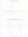
So here is a quick plot of some of the details (generated with Excel). The top plot shows the reactances of the three parallel branches (X_B, being purely inductive, is buried in the noise) as well as the overall reactance that is in parallel with the resistor. Here you can clearly see that the points at which the two branches that have a mix of capacitors and inductors hit peaks if well separated from where the overall combination of the three branches do.

The bottom plot shows the voltage (in dBV) and the phase angle of the total load seen by the supply. Here it can be seen that the overall circuit starts out inductive, becomes capacitive, then inductive, then capacitive, then inductive again (and then stays that way if you look at the plot for higher frequencies). Notice how the points of minimum and maximum voltage response are not tightly related to the peaks in the responses of the individual branches. Furthermore, while the peaks in the overall response are correlated with the peaks in the overall reactance that is in parallel with the resistor, this is because the response is then determined by the resistor, as it is now in parallel with a large reactance. But the minimum in the voltage response is not correlated with these transitions at all. The first one, near 37 Hz, looks like it is correlated with the transition in X_A, but this is coincidence, as can be evidenced by the final low around 50 Hz clearly being well away from any of these peaks. This is because the minimum response is related to when the reactance goes to zero (because now we have zero reactance in parallel with a fixed resistance) and this occurs pretty gradually as the total reactance slowly transitions from capacitive back to reactive.
 

Thread Starter

Xenon02

Joined Feb 24, 2021
504
View attachment 274325

So here is a quick plot of some of the details (generated with Excel). The top plot shows the reactances of the three parallel branches (X_B, being purely inductive, is buried in the noise) as well as the overall reactance that is in parallel with the resistor. Here you can clearly see that the points at which the two branches that have a mix of capacitors and inductors hit peaks if well separated from where the overall combination of the three branches do.

The bottom plot shows the voltage (in dBV) and the phase angle of the total load seen by the supply. Here it can be seen that the overall circuit starts out inductive, becomes capacitive, then inductive, then capacitive, then inductive again (and then stays that way if you look at the plot for higher frequencies). Notice how the points of minimum and maximum voltage response are not tightly related to the peaks in the responses of the individual branches. Furthermore, while the peaks in the overall response are correlated with the peaks in the overall reactance that is in parallel with the resistor, this is because the response is then determined by the resistor, as it is now in parallel with a large reactance. But the minimum in the voltage response is not correlated with these transitions at all. The first one, near 37 Hz, looks like it is correlated with the transition in X_A, but this is coincidence, as can be evidenced by the final low around 50 Hz clearly being well away from any of these peaks. This is because the minimum response is related to when the reactance goes to zero (because now we have zero reactance in parallel with a fixed resistance) and this occurs pretty gradually as the total reactance slowly transitions from capacitive back to reactive.
X_T is a total reactance right ? So for most of the frequences the total reactance is equal 0 ? Or maybe I see it wrong ?

Also so if the peaks of individual branches doesn't determine the resonance then the peaks of a total reactance do determine if the circuit is in resonance ? If yes, then which peak says what ? There are as I can see 4 peaks for X_T. Which is reactance for maybe 32 Hz as I can see and it is maybe 1000 omh, for 33 Hz which is -2500 ohm, 46 Hz 46,5 Hz.

For example Vs = 60 for 37 Hz it is not correlated to total reactance. Or Vs for 50 Hz it is minimum but it is not correlated with X_T peak.

Because as I understand here the peaks of Vs are in phase 0 degree like in purely resistance circuit ?


Where is the moment that this is resonance so it is purely resistant or very close to it ? Because it is shifting from inductive to capacitive, inductive and capacitive.
 

WBahn

Joined Mar 31, 2012
33,234
X_T is a total reactance right ? So for most of the frequences the total reactance is equal 0 ? Or maybe I see it wrong ?
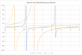
Don't get fooled by the scale. To show the peaks the plot is zoomed out. If we limit the plot to +/- 1000 Ω (comparable to the resistor), it looks like this:

1661042514343.png

The inductors are all just 400 mH and so at 60 Hz their reactance is about 150 Ω. In this case, it's the capacitors that are really driving things.

Also so if the peaks of individual branches doesn't determine the resonance then the peaks of a total reactance do determine if the circuit is in resonance ? If yes, then which peak says what ? There are as I can see 4 peaks for X_T. Which is reactance for maybe 32 Hz as I can see and it is maybe 1000 omh, for 33 Hz which is -2500 ohm, 46 Hz 46,5 Hz.

For example Vs = 60 for 37 Hz it is not correlated to total reactance. Or Vs for 50 Hz it is minimum but it is not correlated with X_T peak.

Because as I understand here the peaks of Vs are in phase 0 degree like in purely resistance circuit ?
Look at where the X_T goes infinite (or tries to -- keep in mind the limits of doing the calculates at sample values of frequency) and where the X_T value crosses zero.

Where is the moment that this is resonance so it is purely resistant or very close to it ? Because it is shifting from inductive to capacitive, inductive and capacitive.
At the transitions between those regions of behavior.

Which transitions are important depend on what you are trying to accomplish with the circuit.
 

Thread Starter

Xenon02

Joined Feb 24, 2021
504
Don't get fooled by the scale. To show the peaks the plot is zoomed out. If we limit the plot to +/- 1000 Ω (comparable to the resistor), it looks like this:

1661042514343.png


The inductors are all just 400 mH and so at 60 Hz their reactance is about 150 Ω. In this case, it's the capacitors that are really driving things.
Oh at this scale it's easier to look at the Vdb.


Look at where the X_T goes infinite (or tries to -- keep in mind the limits of doing the calculates at sample values of frequency) and where the X_T value crosses zero.
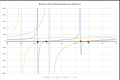
Looking at this scale I can see that X_T has crossed 4 times zero.

1661043399251.png

X_T wants to go "infinite"also 4 times ? 2 times for negative and 2 times for positive.

So which one is the resonance ? There are 4 times X_T is zero and 4 times X_T is "infinite".


At the transitions between those regions of behavior.

Which transitions are important depend on what you are trying to accomplish with the circuit.
So it is between the transitions.


So the minimum here is that the circuit acts like what? And in Max the circuit acts like what ? A shortened circuit or as a open circuit ? Or maybe it is a different behavior ?

Also I'm slowly understanding what is going on here.
 

WBahn

Joined Mar 31, 2012
33,234
Notice that when Z_T goes to positive infinity, there is a frequency at which it transitions very sharply to negative infinity. In theory, this occurs instantaneously and there is no frequency in between where it is zero. That zero is an artifact of making a graph that is just connecting dots between closely sampled points. That nearly vertical line should really be perfectly vertical and should be dashed to indicate that it is not actual values.
 
Top