Can someone correct my view of resonance.

Thread Starter

Xenon02

Joined Feb 24, 2021
504
Correct me if you can sometimes my english is pretty sloppy.


So multiple parallel branches can't combine to give a net zero impedance unless at least one of the branches has zero impedance.
So parallel branches won't give me new frequency for zero impedance but new infinite impedance.


But what about the total impedance going to infinity? This can happen if either the numerator goes to infinity or the denominator goes to zero. The numerator can only go to infinity if one of the two impedances goes to infinity and we are back to the infinity/infinity case which we know reduces to just the other impedance. But the denominator CAN go to zero while both impedances remain non-zero and finite, so multiple parallel branches CAN combine to create an infinite impedance even while the individual impedances each have finite values.
If I understand here.
Combining parallel branches can give me overall infinite impedance. But the individual branches can have finite value, so from 3 branches in parallel I can have many new frequences for infinite impedance because there can be many combinations of finite values of individual impedance of branches ?
So for example I could have more than 2 infinite impedance in 3 parallel branches ?
Because in my circuit with 3 branches I had 2 impedance infinite not one so I was curious how and why is it like that because the difference in branches is only 2 capacitors : one with 50 uF and second one with 100uF. So how is it possible to get 2 infinite impedance from combination of 3 parallel branches (3 of them have to create infinite impedance at specific frequency).

In a individual branch can I have 2 frequences for 0 impedance ?

Also what is the frequence value of infinite impedance ? I wanted to try it on my simulator : https://tinyurl.com/2n2yg2gz
 
Last edited:

WBahn

Joined Mar 31, 2012
33,236
So parallel branches won't give me new frequency for zero impedance but new infinite impedance.
It CAN give you a new frequency for infinite impedance.

Combining parallel branches can give me overall infinite impedance. But the individual branches can have finite value, so from 3 branches in parallel I can have many new frequences for infinite impedance because there can be many combinations of finite values of individual impedance of branches ?

So for example I could have more than 2 infinite impedance in 3 parallel branches ?
Yes. It depends on how complicated each branch is. Notice in this circuit two of the three branches are not simple series LC combinations. There's no guarantee that there IS a frequency at which the impedance goes to infinity; as has been stated over and over, as the circuit gets more complex, it's behavior gets more complex even more quickly.

What is the frequency for infinite impedance ? I want to test in here : https://tinyurl.com/2n2yg2gz
Which impedance????

There are MANY impedances in this circuit. You need to be explicit about which impedance you are asking about.

The overall impedance as seen by the source?

The total impedance of the three parallel branches?

But, if we are talking about the impedance of the three parallel branches, that was plotted out in a couple of places. The zoomed in one was in Post #38 (and copied below).

View attachment 274328

You can see that one of them occurs somewhere a bit over 31 Hz and the other occurs at about 47 Hz.

You can either solve for them analytically, or you can do it numerically using a spreadsheet.

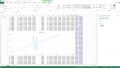
Throwing a quick spreadsheet together shows that the first impedance occurs somewhere between 31.254530802 Hz and 31.254530803 Hz, where the reactance goes from +7.06e11 Ω to -2.00e10 Ω in that 1 nHz span. Now, I'm not sure how accurate those results are because the calculations may well be getting into the roundoff error limits.

I'll let you find the second one. You really need to start taking it upon yourself to do these kinds of things.
 
Last edited:

Thread Starter

Xenon02

Joined Feb 24, 2021
504
Throwing a quick spreadsheet together shows that the first impedance occurs somewhere between 31.254530802 Hz and 31.254530803 Hz, where the reactance goes from +7.06e11 Ω to -2.00e10 Ω in that 1 nHz span. Now, I'm not sure how accurate those results are because the calculations may well be getting into the roundoff error limits.
This frequency worked :D
check it out : https://tinyurl.com/2dr7t2fh


Yes. It depends on how complicated each branch is. Notice in this circuit two of the three branches are not simple series LC combinations. There's no guarantee that there IS a frequency at which the impedance goes to infinity; as has been stated over and over, as the circuit gets more complex, it's behavior gets more complex even more quickly.
I thought that overall impedance for 3 branches that goes to infinity would be only 1 solution but there are 2. So I thought that there could be even more combinations. And to be honest if I wanted only 1 infinity impedance (as an overall impedance) and not 2. It would be very hard to catch which combination causes it. How people do resonance circuit, or maybe I made just to complex ?

Also I asked about zero impedance in individual branch, is it possible to have 2 frequences for zero impedance on individual branch (specific one branch). I thought that if it's possible for 3 branches in parallel to have many frequences for infinite impedance then maybe individual branch also can have many frequences for zero impedance.

PS.

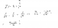
Also is this calculation incorrect ?

1661256946581.png

I thought it would be infinite at the end because infinity/infinity.
 
Last edited:

WBahn

Joined Mar 31, 2012
33,236
I thought it would be infinite at the end because infinity/infinity.
Infinity/infinity is indeterminate. It could be anything. What you need to do in that case is look at the limit as the frequency goes to the value in question.

In this case, it's easy to see from your middle line.

1/Z1 = 1/R + 1/(j*infinity)

What is 1/(j*infinity)? It's zero! This leaves you with

1/Z1 = 1/R

Z1 = R

To understand how to use limits to find the value as you get arbitrarily close to an indeterminate case, look up and study L'Hospital's Rule.
 

Thread Starter

Xenon02

Joined Feb 24, 2021
504
Infinity/infinity is indeterminate. It could be anything. What you need to do in that case is look at the limit as the frequency goes to the value in question.

In this case, it's easy to see from your middle line.

1/Z1 = 1/R + 1/(j*infinity)

What is 1/(j*infinity)? It's zero! This leaves you with

1/Z1 = 1/R

Z1 = R

To understand how to use limits to find the value as you get arbitrarily close to an indeterminate case, look up and study L'Hospital's Rule.
Ok what do you think about the part i said about frequences before equations?
 

Thread Starter

Xenon02

Joined Feb 24, 2021
504
Explore that math!
I just need this last Information :D
Because it is confusing that 3 Branches In parallel can make more than 1 frequency for infinite impedance so I thought that maybe it can work with individual branch which can have more than 1 frequency for 0 impedance.
 

WBahn

Joined Mar 31, 2012
33,236
Consider the reactive portion of your current circuit.

It already has branches that are series/parallel combinations of capacitors and inductors, right?

It already has multiple zeros, right?

So just put that portion of the circuit in a box and call it a branch. You now have a branch that is a series/parallel combination of capacitors and inductors that has multiple zeros.
 

Thread Starter

Xenon02

Joined Feb 24, 2021
504
Consider the reactive portion of your current circuit.

It already has branches that are series/parallel combinations of capacitors and inductors, right?

It already has multiple zeros, right?

So just put that portion of the circuit in a box and call it a branch. You now have a branch that is a series/parallel combination of capacitors and inductors that has multiple zeros.
I meant that individual single branch and not the combination of 3 branches and calling it a 1 branch.

Same goes with parallel branches, 3 branches has to do overall infinite impedance, so I thought that it could be only 1 frequency.
But I wounder why 3 branches can create 2 infinite impedance. Is it controllable ? Is it easy way to find out why there are 2 frequences for 3 branches to become infinite impedance ? Their only difference is only capacitor value.
 

WBahn

Joined Mar 31, 2012
33,236
If you are okay with each of your parallel branches having a series/parallel combination of capacitors and inductors, why are you not okay with a series branch having a series/parallel combination of capacitors and inductors?

If you are going to place restrictions on what this branch can consist of, you need to spell out what those restrictions are!
 

Thread Starter

Xenon02

Joined Feb 24, 2021
504
Okey
So the restriction is that must be one branch not combination of 3 branches into one branch. Just one branch out of 3 branches.
Can it consist more than 1 frequency of 0 impedance ?
 

WBahn

Joined Mar 31, 2012
33,236
But what can that "one branch" consist of?

You seem okay with the current circuit having a parallel combination of a capacitor and inductor as part of what you consider a "one branch". Why is that okay?
 

Thread Starter

Xenon02

Joined Feb 24, 2021
504
But what can that "one branch" consist of?

You seem okay with the current circuit having a parallel combination of a capacitor and inductor as part of what you consider a "one branch". Why is that okay?
Hmm you are probably right. So If I add another component in this one branch (LC in parallel and then L in series) for example I add another capacitor in parallel with inductor (indcutor that was in series with parallel LC). Then I can have another frequency for 0 impedance ?

It's hard to imagine how it works ... and how to controll which branches do what.
I can't even imagine why 3 branches together can have 2 frequences for infinite impedance.

How to controll it ?
 

Halfpint786

Joined Feb 19, 2018
109
When energy is supplied to a capacitor, the voltage across it rises while the current through it drops. When energy is supplied to an inductor, the current through it rises as the voltage across it drops.

The tricky part in visualizing their interaction with eachother is to resist the urge to think about it in terms of instantaneous voltages/currents because they are always changing. It is their ability to pass energy back and forth to eachother that really makes the magic happen.

Take an LC combnation where the L and the C have the same reactance, they handle the same amount of current, just with opposite polarity.

In a parallel LC combination, if the L and the C are handling te same amount of energy, and that energy is in opposing direction, the only energy through them is what is shared back and forth between them. A ton of current can flow within that loop, but there is nothing left to escape the loop because the L and C were equal (and opposite) in reactance. Just like ohms law would suggest for DC, if there were two resistors in parallel carrying the same amount of current, but somehow the current in one was flowing in the opposite direction, this leaves no energy to pass along to the next component in the circuit as the two forces cancel each other out. This inability to pass current to the next stage is what gives the parallel combination it's "apparent" high impedance.

When you put them in series, the current across one is not in direct opposition to the other because there is a load or another component in the loop. When one is discharging, that energy goes to charging the other, but that energy must also flow through the rest of the loop (like the load). This gives the combination it's "apparent" low impedance.

When the charging and discharging of the L and the C take the same amount of time, they are said to be in resonance. However, if it takes a different amount of time (their reactances are not the same), the ability of the LC combination to pass current will be somewhere in between the two extreme cases.

For series combinations, their total reactance will simply be the sum of their individual reactances (with capacitive reactances being negative values), whereas parallel combinations will be just like parallel resistances, you add the reciprocals and take the reciprocal of that sum (again, capacitive reactances being negative).

Hope that makes sense.
 
Last edited:

sparky 1

Joined Nov 3, 2018
1,218
In a resonant RLC circuit the magnitude of L and C's reactance cancel. So, it can be helpful to have both L and C reactance's equal.
We can indicate LC canceling with a peak voltage test.

However, when R is not zero the phase angle begins to change. In practice we simply try to keep the R value down.
You can build a very low load circuit, but it has little practical value with exception of being an accurate frequency source.

In a power circuit where energy is concerned and not just amplifying a signal, we have to expand the mathematical expression.
Here are just a few such expressions: Impedance and Admittance Formulas for RLC Combinations - RF Cafe

You are not completely incorrect showing a material's resonant spurs. There are series and parallel resonances, and some materials have multiple spurs for example a ceramic resonator vs crystal. To look at a view of a specific resonance would not in every case be generalized. For an expression to be correct a fully detailed expression will better define a specific case.

A student of physics going for electrical engineering may only have generalized physics lab experience and later find that there is much more.
That would not mean he or she has an entirely incorrect view. Here is one lab that covers a quite a bit.
Microsoft PowerPoint - 2054_ch21A.ppt (ufl.edu)

What is expected of a graduate entering the workforce is sometimes the employer's estimation of how you can adapt to their senior scientist level.
How well you grasp the articulation of enineering math gives confidence in understanding a specific approach, specific details regarding a view being correct is not always as important as the mechanics or procedural application being done correctly.
 
Last edited:

Halfpint786

Joined Feb 19, 2018
109
To answer the question in your example, it would be total effect, not the resonances of the individual groups.

What you would do if you wanted to graph this (as I just did in excel) is to combine the parallel reactances of C1 and L1, call that T1. Then combine the reactances of C2 and L4 and call it T2. Add T1 to the reactance of L2 and call that T3. Add the reactances of T2 and L5 and call that T4. Combine the parallel reactances of T3, T4 and L3 and call it T6. Then, find the series equivalents of T6 and R1. Now, find the absolute value of those series equivalents by finding the square root of the sum of their squares and plot those values on the graph. The left axis is in absolute impedance rather than dB because I didn't apply voltage to these calculations.

EDIT: I changed the photo as I switched my horizontal axis to log and extended the freq range so our charts looked the same, I originally had it to 100hz and linear...
 

Attachments

Last edited:

WBahn

Joined Mar 31, 2012
33,236
Hmm you are probably right. So If I add another component in this one branch (LC in parallel and then L in series) for example I add another capacitor in parallel with inductor (indcutor that was in series with parallel LC). Then I can have another frequency for 0 impedance ?

It's hard to imagine how it works ... and how to controll which branches do what.
I can't even imagine why 3 branches together can have 2 frequences for infinite impedance.

How to controll it ?
You do the math.

Analyze the circuit for the impedance in terms of the symbolic quantities (e.g. L2, C3, etc.) and then you look at the equation and ask what conditions, if any, will result in the overall result going to zero or going to infinity, depending on what you are looking for.

If you are designing the circuit, you do so using building blocks that behave the way you want (though you need to be aware of the possibility of unintended interactions).
 

MrAl

Joined Jun 17, 2014
13,809
Hmm you are probably right. So If I add another component in this one branch (LC in parallel and then L in series) for example I add another capacitor in parallel with inductor (indcutor that was in series with parallel LC). Then I can have another frequency for 0 impedance ?

It's hard to imagine how it works ... and how to controll which branches do what.
I can't even imagine why 3 branches together can have 2 frequences for infinite impedance.

How to controll it ?

Hello there,

The answer can be very simple if i understand you right.

It may be that you are looking at individual sections and thinking that they work independently of one another, so when one section Z1 is at infinity, the other section Z2 would not yet be at infinity because it has a 'different' resonant frequency and because they are in parallel the entire circuit can not be showing an infinite Z.

Is that right?

Because if it is, then that's the problem. The sections ALONE may show different resonant peaks, but once you connect them together they are no longer INDIVIDUAL they work as a team. That probably also alters both peak points as well because each 'section' not only acts on it's own it is also influenced by the other sections so we see an entirely different response.
You may have to look closely to see this though. The peaks could be far apart or close to the way they work individually.

To find out, run what you think the individual sections are INDIVIDUALLY and note the peaks.
Then run them together and note the peaks.
See what difference it made in the peaks to connect them together.

Keep in mind that i have not analyzed this circuit yet so i dont know yet if they really are infinite peaks at any point, but if they are, or they are just 'high', then we could see the same action just with high peaks that may be mistaken for infinite peaks.

So test them individually, then together. See if the peaks move.

The way to control it is to do an analysis of the entire circuit and check for the peaks, then develop an equation for the two peaks if possible. In that way you should also be able to get a circuit that has just one peak if that's what you want.

A good question i think is what do you want to use this for. There may be simpler ways to get there.
 
Top