Can I power LEDs of different forward voltages connected in parallel with a single constant current source?

Thread Starter

ISHRAQ6251

Joined Aug 24, 2023
11
I am a complete beginner at designing circuits and my English sounds like a 5-year-old talking. So, please beer with me.

I was thinking of building an aquarium light. As plants need a full spectrum of light to grow properly, this is the selection of colours I came up with by watching many YouTube videos about this topic. I also wanted to adjust each colour separately with an Arduino or esp8266.

The first problem was to control these LEDs based on colour. Which I think I have solved with help from the internet. Please check if there are any problems with the Mosfet driver section.

I am planning on powering these LEDs with a voltage and current-controllable buck converter. (The LEDs are 1W each. They are bead-type LEDs commonly used in horticulture)
Now the problem is the red and the yellow LEDs have a lower forward voltage than the rest and there is also a smaller number of yellow LEDs. So, my questions are:

1. Won't there be a lower resistance path through the red and yellow LEDs for the current to flow? Which in turn will make them brighter than the rest or possibly even damage them.

2. Is it ok to power LEDs with a higher voltage than the sum of forward voltages as long as the current is constant?

3. Is it ok to connect LEDs in parallel like in the schematic?

4. If this won't work, what are the other options I have to accomplish the goals I have?

5. And if this works (which I don't think it would) is the voltage and current (20.4V 12.6A) I'm planning on providing correspond with the need of the circuit?

Thanks in advance.

View attachment fsdgsdgn.png
 

Attachments

ronsimpson

Joined Oct 7, 2019
3,257
Looking at your schematic, there is no constant current source.
3. Is it ok to connect LEDs in parallel like in the schematic?
Yes and no. The LEDs that are paralleled must have the same voltage drop. If all your LED have the same date code and were from the same wafer then paralleling works.
2. Is it ok to power LEDs with a higher voltage than the sum of forward voltages as long as the current is constant?
If you have a constant current source, then yes, but I don't see one in your work.

LEDs are current devices not voltage devices. You should never just put a voltage across a LED.
For most of you LEDs there are 6 in series. So the LED will reach full power at 18 to 20.4 volts but you don's know exactly what voltage.
If your LEDs are low voltage (18V) they will burn out at 20.4V.
In the case of red and yellow you will burn out the LEDs. Too much voltage.

Paralleling LEDs of different colors is not a good idea. You need a CC for each group of LEDs.
 
Last edited:

MisterBill2

Joined Jan 23, 2018
19,588
The simple scheme is to not use a constant current source at all. But it WILL require a bit of measurement and some math as well. But if you already have the LEDs then that is the difficult part. You need to know the voltage drop for each color LED you will be using, as well as the current that you plan on operating the LEDs at. Then you also need to know the VOLTAGE of the power supply that you intend to use to power them.
Now comes the hard part: For each string of lights, see how many in series it will take to add up voltage drops to a bit less than the power supply voltage.
So if your LEDs have a 3.1 volt drop and your power suppy is 12.0 volts then the string will drop 9.3 volts with three LEDs and you would need to drop 2.7 volts across a series resistor to provide exactly the desired current. But if your supply was set to 12.5 volts then you could have 4 LEDs dropping 12.4 volts and use a much lower value resistor to drop the remaining 0.1 volt.
This would be done for strings of each selected color. Then each string would be connected across the power supply.
 
Last edited:

LowQCab

Joined Nov 6, 2012
4,346
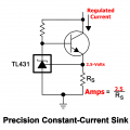
Place this Circuit between the LEDs and your existing Switching-FETs ...........

Your Power-Supply should have the Voltage Set so that
you have the minimum-Voltage required when maximum LED Light-Output is demanded.
.
.
.
Precision Current Sink .PNG.
 
Last edited:

dl324

Joined Mar 30, 2015
17,220
Is it ok to connect LEDs in parallel like in the schematic?
Not unless the LEDs are matched for forward voltage.

Having LEDs from the date code, wafer, or lot of wafers isn't sufficient. Process variation will give multiple forward voltages and brightnesses on the same wafer. Wafers processed on the same date will have no better matching than die from the same wafer. It's more common for LEDs to be binned (sorted) by brightness than by forward voltage because the preferred method for driving LEDs is with a current source which makes variations in forward voltage less important.
 

Thread Starter

ISHRAQ6251

Joined Aug 24, 2023
11
Looking at your schematic, there is no constant current source.

Yes and no. The LEDs that are paralleled must have the same voltage drop. If all your LED have the same date code and were from the same wafer then paralleling works.

If you have a constant current source, then yes, but I don't see one in your work.

LEDs are current devices not voltage devices. You should never just put a voltage across a LED.
For most of you LEDs there are 6 in series. So the LED will reach full power at 18 to 20.4 volts but you don's know exactly what voltage.
If your LEDs are low voltage (18V) they will burn out at 20.4V.
In the case of red and yellow you will burn out the LEDs. Too much voltage.

Paralleling LEDs of different colors is not a good idea. You need a CC for each group of LEDs.
Thanks for the quick reply.

The constant current sources I would like to use is a commercial voltage and current-controllable buck convert and it is not shown in the schematic. I just wrote the current value that I would limit it to on the power rail.

Happy to know that this method would work for a bank of LEDs with same color. I guess I will just power ever color of LED with a separate buck converter.
Please let me know if there is a better and more cost-effective way to do this. And also is the mosfet driver circuit ok?
 

LowQCab

Joined Nov 6, 2012
4,346
"" I guess I will just power every color of LED with a separate buck converter. ""
That will work just fine,
or,
You can individually set the required Currents with the simple Circuit addition that I provided in post #4,
that way You can simplify the whole setup, and keep your present Components as they are.
.
.
.
 

Thread Starter

ISHRAQ6251

Joined Aug 24, 2023
11
"" I guess I will just power every color of LED with a separate buck converter. ""
That will work just fine,
or,
You can individually set the required Currents with the simple Circuit addition that I provided in post #4,
that way You can simplify the whole setup, and keep your present Components as they are.
.
.
.
Thanks a lot for the circuit. The problem is that I don't understand this circuit. I will for sure try to learn about it.
 

Thread Starter

ISHRAQ6251

Joined Aug 24, 2023
11
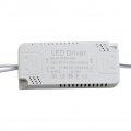
Is it possible to use something like this:
575014064381461159 (1).jpg
These are readily available in my country. There is an output voltage range of DC180-240V written on the device does that mean I can use a string of LEDs with a forward voltage within that range? Are these devices safe? Are they efficient? And most importantly will I be able to use the existing PWM dimming system I have? (Of course with a MOSFET of greater voltage rating) 575014064381461159 (1).jpg
 

LowQCab

Joined Nov 6, 2012
4,346
The only thing left-out of the Schematic is the value of the Transistor-Bias-Resistor,
this will depend to a large extent on the Power-Supply-Voltage, and the chosen Power-Transistor,
however, I'm not particularly qualified in the operation of BJT-Transistors,
but there are plenty of guys here who are geniuses at calculating and selecting BJTs.

This same Circuit could be done with a MOSFET,
but the Forward-Voltage-Losses would certainly be higher than a BJT.

The Gate-Driver, and the FET, could also easily be completely replaced with a common Buck-Converter-Chip
set up to act as a Switch-Mode-Current-Regulator, with very high efficiency.

It can be dimmed by a Logic-Level-PWM-Signal on the "Enable-Pin" ( not shown in the Schematic )
.
.
.
5A 60V Current Source .png.
 

LowQCab

Joined Nov 6, 2012
4,346
The White-Modules shown are apparently not "Dimmable",
they generate 300mA of Current at all times.

The Input-Voltage is irrelevant.
The Output-Voltage is extremely high though, and this will very likely create a disastrous problem.

These devices are designed to operate with a matched LED-Light-Fixture,
they are NOT generic Power-Supplies.
.
.
.
 

ronsimpson

Joined Oct 7, 2019
3,257
There are many options that require some education:
--Use a LED strip and program a micro computer like Arduino.
--Wire up a small printed circuit board.
--Find the right off the shelf dimmable CC power supply.

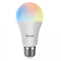
Here is what I am doing. There are many LED color light bulbs. I am using "SONOFF B05-BL-A19 Wi-Fi Smart RGB Bulb 9W Variable Color, 2700K - 6500K Brightness Adjustable Color Temperature, APP Remote Control". This one can be set to any color and power level from your cell phone. They have an internal timer so they can be set to turn on/off at a certain time. If you set up an account, they can be set to come on at Sun up/down.

Some of the LED color bulbs only give you different shades of white, and some will go Red/Green/Blue. I use some in white mode and reduce the brightness way down. Most I use in "Christmas colors".

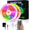
I have heard of some other types of bulbs that can be programmed to randomly change colors or track music.
1707228760012.png
I have not tried these.
1707230103407.png
 
Top