Can I charge 2 cell Battery (3.7V 5000mAh) with SLM6800?

Thread Starter

fadhilfirdausi

Joined Jul 14, 2026
2
Hi, I'm sorry if the question is a little bit basic. But I'm really a beginner and don't know where to start, and this is my first post. I've done PCB design before but only following the datasheet. Now I'm handle a real job and has to continue the design that left by the previous engineer. I have so many question about the design.

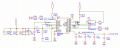
The device is ESP32 battery powered, and now I want to focus on the charging module. The battery used is 2 cell 3.7v 5000mAh in series, so it will produce 7.4v. the question is, is it a good choice to charge this battery with the SLM6800? and things that made me confuse is the usage of 2.2uH inductor instead of 1uH recomended by the datasheet. and the multiple decoupling and bulk capacitor, is it really need to be this much? (C117 and C116 is 100uF)1784030098952.png
 

ericgibbs

Joined Jan 29, 2010
21,541
hi fad,
Welcome to AAC.
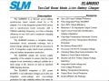
This clip from the d/s should cover reason for the 2.2uH usage.
The capacitive filter for the input and output voltages does seem a 'little over the top' compared to the d/s.
E
EG 2145.jpg
 

Thread Starter

fadhilfirdausi

Joined Jul 14, 2026
2
hi fad,
Welcome to AAC.
This clip from the d/s should cover reason for the 2.2uH usage.
The capacitive filter for the input and output voltages does seem a 'little over the top' compared to the d/s.
E
View attachment 369495
Hi Eric, thanks for the answer, and thanks for providing the datasheet in english, since what i found was in chinese and i couldn't read it. About the capacitive filter, the previous engineer mention about the EMI problem, do you think these capacitors added to solve the EMI? and another question, is one of each value of capacitor enough to filter the noise? what is the purpose of adding multiple capacitor with the same value? (like in this case 3x22uF on the input and 3x100nF on the output)
 

ericgibbs

Joined Jan 29, 2010
21,541
hi fad,
Attached copy of d/s in English for reference.
Ref the EMI, if the charger circuit was drawing power say from the PC's USB port and possibly the Battery was supplying power to the ESP32, while charging, some extra input/output decoupling would be a wise move.

E
 

Attachments

cwella

Joined Jul 9, 2026
25
Hi, I'm sorry if the question is a little bit basic. But I'm really a beginner and don't know where to start, and this is my first post. I've done PCB design before but only following the datasheet. Now I'm handle a real job and has to continue the design that left by the previous engineer. I have so many question about the design.

The device is ESP32 battery powered, and now I want to focus on the charging module. The battery used is 2 cell 3.7v 5000mAh in series, so it will produce 7.4v. the question is, is it a good choice to charge this battery with the SLM6800? and things that made me confuse is the usage of 2.2uH inductor instead of 1uH recomended by the datasheet. and the multiple decoupling and bulk capacitor, is it really need to be this much? (C117 and C116 is 100uF)View attachment 369494
The first thing I’d check is whether the SLM6800 is actually suitable for a 2S Li-ion pack. A 2-cell series battery is 8.4V fully charged, so the charger IC must support a 2S charging profile and the correct charge voltage/current. Don’t assume based only on the battery voltage.

The inductor value change from 1µH to 2.2µH may have been intentional. It can affect ripple current, efficiency, and switching behavior, but you’d need to check the IC’s switching frequency, current rating, and the designer’s calculations. It’s not always a mistake.

For the capacitors, designers often add extra bulk capacitance near power stages because switching converters create high current pulses. The large 100µF capacitors may be for input/output ripple reduction or battery transient response. They may not all be strictly required, but removing them without checking the power requirements can cause instability or noise issues.

Since you inherited the design, I’d start by tracing the charger section:

Confirm battery chemistry and configuration (2S Li-ion/LiPo).
Check charger IC voltage/current limits.
Compare the schematic values against the datasheet reference design.
Look at PCB layout around the IC, inductor, and capacitors.

The previous engineer may have changed values based on testing, so understand the reason before modifying anything.
 
Top