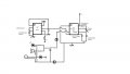
Can anyone tell me with this isn't working?

AnalogKid

Joined Aug 1, 2013
12,238
The 3905 datasheet recommends a maximum capacitor size of 100 uF. This would require a 36 Mohm resistor for a 1 hour period. As noted above, this is *very* difficult to work with. Consider an oscillator/divider like the CD4060 to generate the 1-hour period.

ak
 

AnalogKid

Joined Aug 1, 2013
12,238
The 20K Ohm trimmer is 20 turn to adjust it to 40Hz to a value of I think 13.5K Ohm to get an even sqaure wave.
The 555 circuit in post #1, even when corrected, will not make an "even" (50/50) symmetrical square wave. In the datasheet for the CMOS LMC555, there is a circuit for that.

ak
 

MrChips

Joined Oct 2, 2009
35,018
How accurate do you need the 40Hz and 1-hour to be?

Electrolytic capacitors make very poor timing elements. You would be better to use a high frequency oscillator and then divide that down to give a 1-hour time duration. Look at a CD4060 oscillator and binary divider as an example.

Edit: AK beat me to it.
 

Thread Starter

Halsey

Joined Mar 4, 2018
30
The 3905 datasheet recommends a maximum capacitor size of 100 uF. This would require a 36 Mohm resistor for a 1 hour period. As noted above, this is *very* difficult to work with. Consider an oscillator/divider like the CD4060 to generate the 1-hour period.

ak
Thank you. I'm quoting a book called Basic Electronics Theory: "The only limitation is the practical maximum value of the timing components. For example, you'd have a hard time finding a 2 F capacitor or a 330M Ohm resistor." Though I suppose the datasheet specs are the real values, I've never worked with it before.
 

Thread Starter

Halsey

Joined Mar 4, 2018
30
How accurate do you need the 40Hz and 1-hour to be?

Electrolytic capacitors make very poor timing elements. You would be better to use a high frequency oscillator and then divide that down to give a 1-hour time duration. Look at a CD4060 oscillator and binary divider as an example.

Edit: AK beat me to it.
I'm less interested in the hour than I am the 40Hz, I was goining to use a 330uF capacitor and a 10Mohm in series with a 2Mohm 25 turn trimmer. Though I've read that electrolytics can be problematic Are you refering to the 3905 or 7555 CMOS. From what I understand the CMOS is applicable to any 555 DIP timer circuit, but the reve5rse is not true. I think I may have meant 17.5k Ohms, I have the value written down somewhere.
 

Thread Starter

Halsey

Joined Mar 4, 2018
30
DIsregard the rest of the circuit, it is supposed to power a speaker, two LED's and a Small DC motor, eventually.
 

AnalogKid

Joined Aug 1, 2013
12,238
I don't understand. If the 555 is oscillating fast enough to produce an audible tone, that signal cannot drive a motor.

ak
 

Thread Starter

Halsey

Joined Mar 4, 2018
30
I don't understand. If the 555 is oscillating fast enough to produce an audible tone, that signal cannot drive a motor.

ak
The motor may be stretch, but I have powered two leds and headphones with a 555 dip timer and had to add resistors for the LED's and headphones. It's a sqaure wave so low tones are quite audible, even at 40Hz its pretty loud. The schematics are a rough draft and there are obvious problems in the power consumption by driving all the components. I just completed a working circuit that times and ocsiallates at 40Hz, but with .20mA I don't see it driving the rest of the components. I know you can controll the voltage output at pin 5 and maybe with some power transistors can help generate the nessesary power to drive a motor at roughly 2400 rpm's.
 
Top