Can anyone help me debugging the astable multivibrator simulation using LTspice for 32KHz frequency 50% duty.

MrChips

Joined Oct 2, 2009
30,621
You have R1 and R2 connected to the wrong pin of the transistor. They should be connected to the base of the transistor, not the collector.

Change R1 to 47kΩ.

Post the link to where you found this circuit so that we can confirm this.
 

Thread Starter

mishra87

Joined Jan 17, 2016
1,034
You have R1 and R2 connected to the wrong pin of the transistor. They should be connected to the base of the transistor, not the collector.

Change R1 to 47kΩ.

Post the link to where you found this circuit so that we can confirm this.
Hi,
I tried using some reference circuit over internet.
No specific link.
Could you please try ltspice in attached file in #post1
 

Audioguru again

Joined Oct 21, 2019
6,647
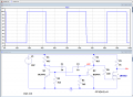
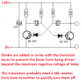
Your 10V supply voltage is too high or base protection diodes are missing since the datasheet for the BC547 says the maximum allowed reverse emitter-base voltage is only 6V and your circuit and the simulator is making it 9.3V.
The simulator might not know that the transistors are slowly being destroyed.
 

Attachments

AnalogKid

Joined Aug 1, 2013
10,971
Note that in all of the suggested schematics:

1. The two collector resistors are equal value.

2. The base resistors are larger than the collector resistors.

None of these things are true with your schematic in post #1.

ak
 

ericgibbs

Joined Jan 29, 2010
18,736
hi agu,
I have deliberately left the clamp diodes off, in order to show the TS, they will be needed..:rolleyes:

I am waiting for his response
E
 

AnalogKid

Joined Aug 1, 2013
10,971
His circuit will NOT give him the results he requires.

He wants a 50:50 square wave at 32kHz
I know. The point I was making is that the circuit will not do what he wants for multiple reasons; there is not just one wrong component value, or one incorrect connection, or, or ,or

ak
 
Top