 Facebook
 Google
 GitHub
 Linkedin
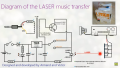
I am a noob in electronics and thought of doing this cool project i saw on youtube. It uses laser for transmission of music from one location and receive it using solar panel on other side.I want to make this and also know the working of this circuit. Please help.
Attachments
-
 844.9 KB Views: 33
")


