Can a Relay designed to allow ac current be used with dc?

Thread Starter

Rimbaldo

Joined Jun 6, 2016
32
Hi!
I'm converting my mini lathe to cnc and I came to a doubt... I've got a 48V DC electromagnetic relay that allows 8A-350VAC of load between its terminals.

But my lathe motor works with 220V DC, not AC. Is it a problem? The relay's coil will be supplied with 48V DC. But the load will be DC instead of AC.

Will this relay work? Or are there specific power relays for DC (coil) and DC (load)?

Thanks

I can't find a datasheet for it: it's marked Schrack ZU200048, but looks exactly like this one attached
 
Last edited:

Sensacell

Joined Jun 19, 2012
3,453
Look up the relay specifications.

Contacts rated for AC and DC applications typically have much lower ratings for DC.
The reason is that DC arcs are not self-extinguishing, AC arcs tend to break rapidly because the voltage crosses zero every AC cycle, giving the arc a chance to quench.

At 200 V, it's going to arc like crazy.
 

Thread Starter

Rimbaldo

Joined Jun 6, 2016
32
Look up the relay specifications.

Contacts rated for AC and DC applications typically have much lower ratings for DC.
The reason is that DC arcs are not self-extinguishing, AC arcs tend to break rapidly because the voltage crosses zero every AC cycle, giving the arc a chance to quench.

At 200 V, it's going to arc like crazy.
Hi! Thanks!

Everytime the relay will be activated, the dc motor (inductive load) will start it's rotation from 0v progressivelly to max 220V. It's not an instantaneous 0vDC to 220vDC. Will the relay generate these arcs even by doing this way? The contacts for AC 350V are not enough for DC max 220V?

Is there a method to prevent these arcs?

Sorry, I don't know a lot on electronics...

Thanks a lot!
 

MaxHeadRoom

Joined Jul 18, 2013
28,698
If switching both on AND off with zero current you could get away with the relay.
Otherwise you would either need some other method or a relay rated for DC switching and in some cases, magnetic arc blow out feature at switch off.
Max.
 

Thread Starter

Rimbaldo

Joined Jun 6, 2016
32
If switching both on AND off with zero current you could get away with the relay.
Otherwise you would either need some other method or a relay rated for DC switching and in some cases, magnetic arc blow out feature at switch off.
Max.
Hi! Thanks! These can be arranged in the cnc mach3 program to slowly start and slowly stop the motor before turning it on and off.

The only scenario it would suddenly stop, and switch off the relay of a sudden would be when pressing an emergency button or some fault the lathe detects (like over current on the lathe's control board).

In these not usual cases, how could I find information on doing this magnetic arc blow out feature?

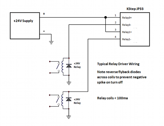
I read in a schematics for doing a cnc retrofit on another lathe (dc 110v motor) to wire a diode in parallel to the poles (but in the coil side of the relay) to prevent spikes... would this be an option? Something like this?


Thanks for helping!
 
Last edited:

MaxHeadRoom

Joined Jul 18, 2013
28,698
In these not usual cases, how could I find information on doing this magnetic arc blow out feature?
Thanks for helping!
The magnetic blow-out relays I have used in the past are made by Potter & Brumfield PRD series.
Otherwise you could use a R/C snubber across the contacts to help eliminate arcing.
Max.
 

Attachments

Thread Starter

Rimbaldo

Joined Jun 6, 2016
32
The magnetic blow-out relays I have used in the past are made by Potter & Brumfield PRD series.
Otherwise you could use a R/C snubber across the contacts to help eliminate arcing.
Max.
Thanks a lot!! A diode in paralel to the coils of the relay is a type of snubber right?

I'll read the pdfs you sent! Thanks!
 
If the motor has a controller feeding it what is the relay for?
You couldnt rely on a contactor for isolation, much less a relay.

Contactrors are a better choice because you have two contacts in series and thus a bigger air gap.

What sort of motor is it?
I ask because if it will generate, which it probably will when free wheeling, it will be very good at maintaining that contact destroying arc, or burning out the diode/snubber for that matter...
Coils are easy because they generate a forward current when you switch them off...
When you energise a coil current starts to flow which builds flux, which in turn preoduces an opposing voltage, thus limiting current untill the current, and thus flus, stops changing. When the voltage is switched the current starts to fall and the flux colapses which generates a forward voltage. Putting a diode accros the switch gives this forward current a path, essentally shorting out the voltage generated by the colapsing flux in the coil and thus limiting the voltage.

Motors are a little harder... when generaating they produce a reverse voltage so a diode cant be used because it would be the same polarity as the motor in normal operation. One strategy is to use a late break normally closed contact, which will be early make when the contactor is opening.
This, places a hefty current limiting resistor in paralell with the motor just before the motor switching contact opens giving any discharge somewhere to go for a while. Adding a MOV, or simmilar, in paralell with the resistor can provide a low impeadence path for voltages that exceed to normal operating voltage of the motor.
That said, if the system can generate then you have to first short it to quench the arc and then lower the current in a controlled manor.
That implies a a capacitor which must be discharged when the motor is on and connected, paralell to the motor, as the switch contact opens.

You need to think carefully about this and/or give more detail.
If this relay is a safety device then you dont want to be mucking about.

This is hard enough that a class of contactor exists specifically for the task...
http://new.abb.com/low-voltage/products/motor-protection/contactors-for-dc-switching

Go easy, 230V DC can easily be leathal and will start fires. Dont underestimate this, it would be a very poor plan.
I dont mean any offence but if you are not aware of the issues and risks you shouldnt be messing with it, because it could kill you.

Hope that helps,
Al
 

Thread Starter

Rimbaldo

Joined Jun 6, 2016
32
If the motor has a controller feeding it what is the relay for?
You couldnt rely on a contactor for isolation, much less a relay.

Contactrors are a better choice because you have two contacts in series and thus a bigger air gap.

What sort of motor is it?
I ask because if it will generate, which it probably will when free wheeling, it will be very good at maintaining that contact destroying arc, or burning out the diode/snubber for that matter...
Coils are easy because they generate a forward current when you switch them off...
When you energise a coil current starts to flow which builds flux, which in turn preoduces an opposing voltage, thus limiting current untill the current, and thus flus, stops changing. When the voltage is switched the current starts to fall and the flux colapses which generates a forward voltage. Putting a diode accros the switch gives this forward current a path, essentally shorting out the voltage generated by the colapsing flux in the coil and thus limiting the voltage.

Motors are a little harder... when generaating they produce a reverse voltage so a diode cant be used because it would be the same polarity as the motor in normal operation. One strategy is to use a late break normally closed contact, which will be early make when the contactor is opening.
This, places a hefty current limiting resistor in paralell with the motor just before the motor switching contact opens giving any discharge somewhere to go for a while. Adding a MOV, or simmilar, in paralell with the resistor can provide a low impeadence path for voltages that exceed to normal operating voltage of the motor.
That said, if the system can generate then you have to first short it to quench the arc and then lower the current in a controlled manor.
That implies a a capacitor which must be discharged when the motor is on and connected, paralell to the motor, as the switch contact opens.

You need to think carefully about this and/or give more detail.
If this relay is a safety device then you dont want to be mucking about.

This is hard enough that a class of contactor exists specifically for the task...
http://new.abb.com/low-voltage/products/motor-protection/contactors-for-dc-switching

Go easy, 230V DC can easily be leathal and will start fires. Dont underestimate this, it would be a very poor plan.
I dont mean any offence but if you are not aware of the issues and risks you shouldnt be messing with it, because it could kill you.

Hope that helps,
Al
Hi!
It's a mini lathe dc 220v motor, rated at 150w, 0.9A. This one:

The relay is not a safety device in this case.

The relay will be wired after the controller chose the speed desired, to allow control of the motor (turn on and off) by a CNC software called Mach3, connected to a cnc controller connected to a computer.

There'll be another relay, probably, after this one to change the direction of the rotation of the motor, but will be wired as normally closed. So it will only be turned on when changing motor direction is desired (seldon used though).

The start-stop of the motor and changing directions will always be (programmed) to start slowly from zero volts and stop slowly from max 200v to zero volts, the same applied to when changing rotation direction.

There'll be switches to allow or not the relays, though using the lathe-cnc in full automatic mode (motor on/off/direction/speed) or semi-automatic mode, where the relays will be bypassed and the lathe will work close to manual mode.

I've seen some diagrams of lathe and mills cnc conversion. Most of them use relays, with a diode wired in the relay's coils.

Like this one, which is a 110v (DC) motor, with higher current. Mine is 220v (DC):


LesJones

Joined Jan 8, 2017
4,190
The speed controller on the mini lathe is not designed to be started at a high speed. The switch is purposely put on the speed control potentiometer so that the motor is switched on at the lowest speed setting and ramped up to the desired speed. With your proposed system the motor can be started at full speed so the starting current will be very high and possibly destroy the power mosfets. It is possible that the CNC board will ramp the speed up from zero to the preselected value after its has closed the motor start relay. You would need lo look at the schematic of the CNC board. This is a link to a web page that contains the schematic of one of the versions of speed control board used on the mini lathe.

Les.
 
I agree with all above... if it is only switching when off load, stopped, then all you need to worry about is current.
That said I would still go with a contactor as opposed to a relay.
 

Thread Starter

Rimbaldo

Joined Jun 6, 2016
32
The speed controller on the mini lathe is not designed to be started at a high speed. The switch is purposely put on the speed control potentiometer so that the motor is switched on at the lowest speed setting and ramped up to the desired speed. With your proposed system the motor can be started at full speed so the starting current will be very high and possibly destroy the power mosfets. It is possible that the CNC board will ramp the speed up from zero to the preselected value after its has closed the motor start relay. You would need lo look at the schematic of the CNC board. This is a link to a web page that contains the schematic of one of the versions of speed control board used on the mini lathe.

Les.
Ok... it´s nice to have this conversation to remove all doubts..

I agree,the speed controller built-in to my lathe doesn´t ever allow the motor to rotate unless it´s in very low speed.
My lathe isn´t any version of the ones in Hoss´ site (I´ve been there a lot!) and from that diagram I posted. I just finalized my own diagram, scavaging information about my lathe/controller/ from all around. I´ve got a big picture now from my lathe.

Let´s go from part to part:

In my lathe, the on-off switch is not located on the potentiometer that controls the speed of the lathe. This potentiometer (in my case) varies from 0-5.5V, and this makes the controller drive the motor.

In my lathe, the on-off switch is merged together with the direction switch, and the FAULT switch, by a rotatory 3-position switch.In my schematics design (based on that one I´ve sent - and modified from that) the relays come after the rotatory switch. So, in my case, the lathe will only be turned on by that switch. And in that switch there´s two wires (FAULT wires) that sense if the motor is set at a high speed or not.

So in my lathe, if I set the potentiometer to full speed (5.5V), and turn off the on-off switch manually to off, the motor will stop. But if I turn it back on again (with the potentiometer still on high speed, the motor won´t turn on. The FAULT sensor lights up (a yellow light) and the lathe doesn´t work anymore, unless you turn the on/off switch to off and put the potentiometer speed to 0. And then turns the switch to on again. Then the FAULT sensor light goes to off state and it allows again the motor to run.

English is not my first language, so am I clear so far?

One more thing is, the lathe won´t be manually operated anymore, at least not fully manually. I will still need to turn it on by this switch (Clockwise-OFF-Counterclockwise + FAULT sensor), and only then CNC software can take control.

And the speed controller will be made by the GeckoDrive G540 board, that has a opto-isolated output/input specially made to be wired on the lathe´s-potentiometer terminals. So the software will take control of the min-max speed. And the software will start-stop the motor in a soft way. And can be programmed to always start from 0 and stop slowly to zero.

The cnc software can be implemented to soft start and soft-stop always. The only case it could stop abruptely is when and emergency-stop would occur, and then the motor relay would imediatelly be disconnected.

Do you care to take a look at my schematics? I´ve just finished it. I still need to add switches to bypass relays when full manual control is needed back. (in my schematics the black-red wire from my cnc controller are inverted positive-negative. It´s because my lathe´s controller is wired this way, inverted. I´ve measured it..

Thanks a lot!
 

Attachments

LesJones

Joined Jan 8, 2017
4,190
First a question.
1 Why does the CNC part have to switch the motor on and off by switching the DC to the motor ? It could achieve the same thing by switching the AC input to the speed control board which would only need an AC rated relay. A even simpler method would be to use a small relay that would be in place of the normal on / off switch. (The one that was originaly on the speed control potentiometer.)
In the schematic in post #16 for the lathe to work in normal mode the CNC board would have to power the motor run relay as it is still in series with the motor when the lathe is being used in manual mode.
When in CNC mode the manual direction switch would have to be in the forward position. (It would also run the motor if the manual switch was in the reverse position but forward and reverse commands from the CNC would then be the wrong way round.
I think having a 2 way 3 pole manual / CNC selector switch would be a better solution then in the manual position the CNC motor run relay could be bypassed and in the CNC position it would not matter what position the manual forward / stop / reverse switch was in.

Les.
 

Thread Starter

Rimbaldo

Joined Jun 6, 2016
32
First a question.
1 Why does the CNC part have to switch the motor on and off by switching the DC to the motor ? It could achieve the same thing by switching the AC input to the speed control board which would only need an AC rated relay. A even simpler method would be to use a small relay that would be in place of the normal on / off switch. (The one that was originaly on the speed control potentiometer.)
In the schematic in post #16 for the lathe to work in normal mode the CNC board would have to power the motor run relay as it is still in series with the motor when the lathe is being used in manual mode.
When in CNC mode the manual direction switch would have to be in the forward position. (It would also run the motor if the manual switch was in the reverse position but forward and reverse commands from the CNC would then be the wrong way round.
I think having a 2 way 3 pole manual / CNC selector switch would be a better solution then in the manual position the CNC motor run relay could be bypassed and in the CNC position it would not matter what position the manual forward / stop / reverse switch was in.

Les.
Ok. To your question number 1:

I don´t know... I though t it made more sense to use the on/off cnc relay closer to the motor. But I didn´t know about relays not being the same for DC at the time. And I based myself as a starting point diagrams from others.

I just tried to plug/unplug the lathe from the outlet. What happens is, even if the lathe is not running at all, zero speed, with the rotatory switch at the OFF position (or at ON either) the yellow light (Fault) always starts lit. So everytime I turn on my lathe, I do have to turn the switch to either directon and off again, to get out of the fault state.

If I wire the relay at the AC part, then everytime the cnc software orders the motor to turn off, I would need to manually turn the switch to off and back to on again, even at no speed at all. So in my lathe, wiring the relay at the AC is possible, but makes it more manual.

Also, there´s no normal ON/OFF switch in my lathe. I didn´t remove it. Mine is this way. There´s not even an ON/OFF switch on the AC part. I plug it in the outlet and the only switch I have is the rotatory one. I can´t replace it with a single relay. In my lathe, the on-off switch is a big rotatory switch, which also closes or opens the contacts of the two wires of the fault sensor, and changes the direction of rotation.

That one that is in the potentiometer is from another mini lathe. In mine, the potentiometer is just a potentiometer, with no on/off terminals.

All the rest you wrote is exactly what I thought. As for bypassing the relays for normal use, that´s exactly what I´m doing! :) The diagram in post 16 doesn´t have them yet. I´m having trouble finding here in Brazil 3 poles x 2 positions (ON-ON) BIG switches. I find easily those micro switches, with 9 terminals. I ordered yesterday from ebay a couple of big ones.

As soon as I finish a new version of the diagram I´ll post it.

But apart from the switches (being done), and apart from putting the relay in the AC part not being practical in my case, any more thoughts or corrections in my diagram? Would the relays work?

Thanks so much for taking some of your time to really analyze this!

PS. This is my lathe:
 

LesJones

Joined Jan 8, 2017
4,190
The third set of contacts on the manual forward / reverse switch function as an on / off switch. (Closed in forward or reverse. Open in the middle off position.) Why can't a small relay perform this function when in CNC mode ? There will only be low voltage across these contacts and a small current through them. (But they must be isolated by a relay as this part of the controller is at mains voltage potential.) I am assuming that there is some form of interlocking to prevent the direction relay changing state while the motor is running. (Either in hardware on the CNC interface board or in the software.)

Les.
 
Top