Calculation of the number of primary coil turns

Thread Starter

Tutor88

Joined Feb 8, 2023
272
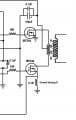
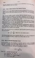
Using a design for a DC-AC HV Inverter, previously developed with the help of this forum, I aim to produce an output of 1kV to 10kV when this is used with a flyback transformer, shown in the other image. However, I'm unsure how to derive the number of turns in each half of the primary with its wind yourself coil.

DC-AC Inverter.png
Flyback transformer.png


I understand that in this setup, the output voltage will be a function of the frequency (via the change in coil reactance) and the output current a function of the duty cycle. I'm aiming for the 10kV output to occur at around 30-35kHz. I believe the following parameters are relevant to the calculation of the number of primary turns:

MOSFET supply: 12.0 - 12.5V

Frequency range: 10kHz - 50kHz

Duty cycle: 10-90%

Idle current: 50-100mA (a guesstimate)

Desired output voltage: 1kV - 10kV

Flyback secondary turns: 2400

Proposed primary coil wire: AWG 16 (1.3mm dia)

Primary former CSA: 2.75cm^2

Any help would be appreciated.
 

MisterBill2

Joined Jan 23, 2018
27,160
At no load and 100% efficiency the voltage ratio will match the turns ratio. In the real world it will not be quite that much. The available output POWER will vary with the duty cycle.
One caution is that for a 10,000 volt output from 2400 turns, you will need to get 4+ volts per turn from that secondary. That may not happen.
 

Thread Starter

Tutor88

Joined Feb 8, 2023
272
At no load and 100% efficiency the voltage ratio will match the turns ratio. In the real world it will not be quite that much. The available output POWER will vary with the duty cycle.
One caution is that for a 10,000 volt output from 2400 turns, you will need to get 4+ volts per turn from that secondary. That may not happen.
So I have no need to derive the inductance of the primary coil and then work out how many turns will produce that? I thought this type of device was very much an inductance-based one. What can I do to improve the volts per turn on the primary out of the FETs? To work out the turns should I just measure the Drain voltage on each FET and take an average?
 
Last edited:

crutschow

Joined Mar 14, 2008
38,316
I thought this type of device was very much an inductance-based device.
It certainly is.
You need sufficient inductance so the core doesn't saturate for the maximum duty-cycle at the primary, i.e. the maximum primary current as determined by its inductance and maximum on-time must not exceed the saturation flux of the core you are using.
Often the core is gapped to increase the saturation point (but, of course, this also reduces the inductance).
 

Thread Starter

Tutor88

Joined Feb 8, 2023
272
It certainly is.
You need sufficient inductance so the core doesn't saturate for the maximum duty-cycle at the primary, i.e. the maximum primary current as determined by its inductance and maximum on-time must not exceed the saturation flux of the core you are using.
Often the core is gapped to increase the saturation point (but, of course, this also reduces the inductance).
Ok, so how do I calculate the turns with the data on the original post?
 

MisterBill2

Joined Jan 23, 2018
27,160
Transformers are certainly INDUCTANCE LIMITED! That is not at all the same as the inductance affecting the voltage ratio. The voltage ratio only applies normally when the core is not saturating. The bad news is that not everything works!!
The good news is that transformer operation and design are quite mature technologies, so there is a lot of excellent information available.
 

MrAl

Joined Jun 17, 2014
13,667
Once I have those then how do I calculate the turns? Is that covered in the above links? I have signed up for the lengthy doc.
Hi,

First, do you own an oscilloscope? You really need that to check if it is working right, or else you have to assume a lot.

If this is your first converter, you can wing it by trying the turns you need on the core and see how it works out. For example, if you try 4 turns then you make sure the core does not saturate. If it saturates you need to go to a higher frequency or get a different core. You can use the Transformer Equation to estimate if your core might saturate.
If you have a core that allows a gap change, you can try added a gap. This cannot be too large however.

If you provide the transformer specs we can help with all this. We need to know the type of material and the cross-sectional area.
 

Thread Starter

Tutor88

Joined Feb 8, 2023
272
Hi,

First, do you own an oscilloscope? You really need that to check if it is working right, or else you have to assume a lot.

If this is your first converter, you can wing it by trying the turns you need on the core and see how it works out. For example, if you try 4 turns then you make sure the core does not saturate. If it saturates you need to go to a higher frequency or get a different core. You can use the Transformer Equation to estimate if your core might saturate.
If you have a core that allows a gap change, you can try added a gap. This cannot be too large however.

If you provide the transformer specs we can help with all this. We need to know the type of material and the cross-sectional area.
Yes, I have a scope. What and where do I measure to see if the core is magnetic flux saturating? When the transformer arrives I will relay the details. I estimated the CSA of the primary in the first post (2.75cm^2).
 

schmitt trigger

Joined Jul 12, 2010
2,027
This transformer topology is not a flyback, but a push pull, and the design process is very different.
Additionally, because the push-pull has a tendency to flux-walking you DO REQUIRE to sense the current on both Mosfets. You can do this by using a resistor in the top Mosfet’s source. And diode-or both signals with a dual schottky diode like the BAT54A.

EDIT; part number correction: BAT54C
 

Attachments

Last edited:
Top