Facebook
 Google
 GitHub
 Linkedin
Hi everyone,
I would appreciate it if you could help me a bit with my assignment.
I've been trying to figure out how to create a traffic light using logic gates with the SL74HC74 Dual D Flipflop, a 555 timer clock signal and proceeding input logic driving 3 LEDs.
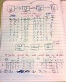
There are 4 states in total (I've also been assigned certain numbers for the corresponding states):
U - Unused state (RED, Wait) (10)
TA - Traffic Active (GREEN, Wait) (00)
TW - Traffic Warning (YELLOW, Wait) (01)
TS - Traffic Stopped (RED, Go) (11)
*With color being for traffic and Wait/Go for pedestrians.
A switch will be used to set the TA state to TW (active high switch).
A switch will be used to set the state machine to the U state.
Inputs will be done with a DIP switch.
I've been tinkering around trying to create a schematic diagram (using logisim) but to no avail.
The state diagram and attempted truth table and Boolean algebra is attached below (I apologize for the messy handwriting!).
As always, thanks for your help!
I would appreciate it if you could help me a bit with my assignment.
I've been trying to figure out how to create a traffic light using logic gates with the SL74HC74 Dual D Flipflop, a 555 timer clock signal and proceeding input logic driving 3 LEDs.
There are 4 states in total (I've also been assigned certain numbers for the corresponding states):
U - Unused state (RED, Wait) (10)
TA - Traffic Active (GREEN, Wait) (00)
TW - Traffic Warning (YELLOW, Wait) (01)
TS - Traffic Stopped (RED, Go) (11)
*With color being for traffic and Wait/Go for pedestrians.
A switch will be used to set the TA state to TW (active high switch).
A switch will be used to set the state machine to the U state.
Inputs will be done with a DIP switch.
I've been tinkering around trying to create a schematic diagram (using logisim) but to no avail.
The state diagram and attempted truth table and Boolean algebra is attached below (I apologize for the messy handwriting!).
As always, thanks for your help!
Attachments
-
 1.6 MB Views: 52