Building an Analog RGB to YPbPr Converter

Thread Starter

aadhoc6180

Joined Feb 27, 2024
5
(Today is National Retro Day)
I'm adding HDMI output to my vintage Atari 800XL 8bit computer to project it on my large TV.

I'm a novice.
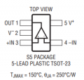
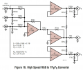
I've built a circuit for "High Speed Analog RGB to YPbPr Converter" using an LT6559 & LT1395 to "map RGB signals to YPbPr".
It doesn't seem to work and it could be because of something I don't know about or how to solve.
(Ugh. I've built & verified it 3 times now)

Could someone provide a suggestion on what to check?

Clarifications:
  • I have added VGA, the source of my Analog RGB (but it does 15KHz, which isn't compatible with most monitors)
  • I have a small RetroTink line doubler that can convert old Component YPbPr signals to HDMI (typical VGA to HDMI adaptors don't work due to 15KHz). RetroTink 2x Classic - https://junkerhq.net/xrgb/index.php?title=RetroTINK2X
  • Together the RetroTink and this circuit are small enough to fit inside the Atari computer, and should have VERY low latency

So far I wonder:
  • Am I powering the parts properly?
    • LT1395 says usually wants +V and -V, but I gave it +5V and G
    • LT6559 says +5V and G are fine
  • Circuit description says I need sync signal embedded.
    • I thought my RetroTink could use signal from Composite input with Component inputs, but that may not be happening.
    • I might not have it, and don't know how to check or fix it.
    • Quote: "As with the previous circuit, to develop a normal
      sync on the Y signal, a normal sync must be inserted on
      each of the R, G, and B inputs or injected directly at the Y
      output with controlled current pulses"

AN57 - Video Circuit Collection
https://www.analog.com/media/en/technical-documentation/application-notes/an57fa.pdf
See Figure 16.

Parts:

Looks simple enough. The surface mount chips were hard, but I got good at it.
I verified everything over-and-over, but the YPbPr Component out doesn't work or look right.
1709015876757.png

Shows my prototype as bread board and in soldered form.
Neither build produces a recognizable signal on Y, Pb or Pr lines.
1709015962720.png

This shows the reasonable red and green signals coming from Analog RGB.
(I don't have typical color bars on hand)
1709016033562.png

(If you ask for details or suggest check this/that, I'll happily check and post results)
 

crutschow

Joined Mar 14, 2008
34,924
LT6559 says +5V and G are fine.
It may say that in the op amp spec, but you can't blindly apply that to this circuit.
The op amp signal must obviously remain within the power supply limits so, for a single plus supply, the signals must all be positive and, since there is an inverter op amp in the converter circuit, that can't be true.
You apparently missed, on the Figure 16 schematic, where It plainly states that the power (Vs) should be ±3V to ±5V.
 
Last edited:

Thread Starter

aadhoc6180

Joined Feb 27, 2024
5
It may say that in the op amp spec, but you can't blindly apply that to this circuit.
The op amp signal must obviously remain within the power supply limits so, for a single plus supply, the signals must all be positive and, since there is an inverter op amp in the converter circuit, that can't be true.
You apparently missed, on the Figure 16 schematic, where It plainly states that the power (Vs) should be ±3V to ±5V.
I see it now. Glad you pointed it out !!
(As a novice, three power leads is new to me, especially since I'm using USB power for this)

So my power need:
  • LT6559 : V+, V-, GND
  • LT1395 : V+, V-
  • Everything else : V+, GND

I just ordered this small Buck Converter from Amazon to do the job... given +5V/GND, produces ±5V/GND
Question: Is that the best way? ... and I just connect the three to ICs as labeled?

(I heard buck converters can cause signal interference. I'll try to mount the converter away from the video circuit)
 

crutschow

Joined Mar 14, 2008
34,924
Question: Is that the best way? ... and I just connect the three to ICs as labeled?

(I heard buck converters can cause signal interference. I'll try to mount the converter away from the video circuit)
Where are you connecting ground for the LT6559?
It should be connected the same as the LT1395.

Yes, switchers can put out high frequency noise, which can appear on power and ground, and moving the converter away from the circuit won't necessarily reduce that.
That type of noise, would be readily seen in the video signal.

Normal practice is to place 100nF ceramic capacitors directly from the op amp power pins to a ground plane to minimize noise.

If possible, it would be better to use a linear supply for the -5V.
 

panic mode

Joined Oct 10, 2011
2,919
Question: Is that the best way?
the best way to use linear regulators. switchers will always have ripple. if you want to use switcher like that, try it. if you do not like the performance (if you see the noise in the image), add different values capacitors across each power rail or consider adding linear LDOs to drop +/-5V +/-3.3V.
 

Thread Starter

aadhoc6180

Joined Feb 27, 2024
5
Where are you connecting ground for the LT6559?
It should be connected the same as the LT1395.

Yes, switchers can put out high frequency noise, which can appear on power and ground, and moving the converter away from the circuit won't necessarily reduce that.
That type of noise, would be readily seen in the video signal.

Normal practice is to place 100nF ceramic capacitors directly from the op amp power pins to a ground plane to minimize noise.

If possible, it would be better to use a linear supply for the -5V.
Before I was wiring
  • all GND and V- to USB supply ground
  • all V+ to USB supply +5V.

The LT1395 doesn't have a GND connection. I was using GND at pin2, but I'm now convinced it needs -5V.
1709158299188.png

I'm not sure how to find a small "embeddable" linear supply that takes +5V, and provides -5V.
(I just searched and only found desktop-sized power supplies)
Question: Could you point me to one?

I like the capacitor as a fallback idea.
Question: Any 100nF ceramic capacitor that's rated at 5V or more?
 

Thread Starter

aadhoc6180

Joined Feb 27, 2024
5
There aren't any because you can't use a linear supply to generate -5V from +5V. It has to be a switching type.

What is the source of your USB 5V power?
Just a quality wall charger https://www.amazon.com/dp/B0B5SQMCXG
The old Atari 800XL used a 1.5Amp 5V DC supply, so a typical hack is to change the power port.
I got that one because it said 3Amp, but I don't know if USB negotiation would be needed to bump it up to 3Amp.
I'll try my "Kill a Watt" to see what it's consuming.
 

Thread Starter

aadhoc6180

Joined Feb 27, 2024
5
It may say that in the op amp spec, but you can't blindly apply that to this circuit.
The op amp signal must obviously remain within the power supply limits so, for a single plus supply, the signals must all be positive and, since there is an inverter op amp in the converter circuit, that can't be true.
You apparently missed, on the Figure 16 schematic, where It plainly states that the power (Vs) should be ±3V to ±5V.
I attached the -5V properly to the two chips last night, and I'm now seeing a GLIMMER of success !!
(I swear this thing is teasing me every step of the way)

I looked at the YPbPr outputs on my cheapo scope, and the signals were finally there, but VERY LOW levels.
I attached the outputted Y/Pb/Pr to my RetroTink Component to HDMI converter, and it produced nothing.
Gave a sync line to the RetroTink... and it started to work.
The boot screen was SLIGHTLY visible, then nothing after that.

The sync line has no image, so the image I saw MUST be coming from the Y/Pb/Pr.
And I can see the image info & embedded sync on my scope.
I'm soldering a new board because my breadboard is unreliable.
I'll post results when its built.

Question: Can I use 28AWG wire for everything?
(I'm seeing that it's rated for over 2amps, so should be fine right?)
 
Top