 Facebook
 Google
 GitHub
 Linkedin
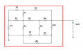
For an upcoming test we are required to build a resistor network on a breadboard, do some measurements and then work out a replacement network and build that after which we need to do the measurements again to ensure we got it right.
We got an example of what we can expect which made my hair go grey :/ Normally (if i got it right) it should be attached to this post.
This is one similar to the network we are getting on the test, though that one will probably have set values for the resistances and sources.
So my question would be how to go about on simplifying this network?
Attachments
-
 16.3 KB Views: 18


