Building a home made charger at European frequency

BobTPH

Joined Jun 5, 2013
11,666
Well im looking for the circuit of the rectifier.I can always use a inductive or capacitive voltage divider(to not waste heat) to reduce the voltage to appropriate levels.
Not unless the current draw is constant, which it is not. You need to read up on switching supplies. You need a separate oscillator with controllable duty cycle and feedback. The line frequency does not help you.
 

Thread Starter

Samantha Groves

Joined Nov 25, 2023
174
If I had a inductive divider with low thevenin impedance then the load doesnt matter.I mean true the current will depend on the load but I dont know more to build something more sophisticated.
 

MisterBill2

Joined Jan 23, 2018
28,508
OK, and a couple of things to consider: First, the inlet power is 240 volts, or maybe only 220 volts, while the output would be 5 volts. Thatis a 45:1 step down. Certainly it can be done with a switcher, and even MORE CERTAINLY the circuit must be very stable and reliable, meaning none of the components should be highly stressed. I agree with Alec_t, except that I recommend a step-down transformer. Certainly the five volt chargers ARE CHEAP, and if they have a transformer it IS a small one, since the load is only one half of a watt. So a small transformer and an adjustable linear regulator will not be as efficient, BUT you can probably get it working right on the very first go. I doubt THAT EVER HAPPENS with switcher supplies designs.
 
Last edited:

Ian0

Joined Aug 7, 2020
13,310
If you want 1A from the mains, using an inductive ballast, it will be about the same size as a ballast for 100W lamp (as discharge lamps tend to run at about 100V), and a ballast for 100W fluorescent or metal halide lamp is a sizable chunk of iron, probably about 1kg.
 

BobTPH

Joined Jun 5, 2013
11,666
An, at low voltages, it will act as a constant current source. Not useful as a phone charger, which needs a constant 5V.
 

MisterBill2

Joined Jan 23, 2018
28,508
We all need to understand that what the TS is wanting is the design for a FIVEVOLT, 100 MILLIAMP PHONE CHARGER circuit. That was not mentioned in post #1.
 

Ian0

Joined Aug 7, 2020
13,310
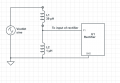
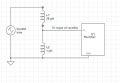
Unfortunately, you will have a standing current of 18000A in your divider, which might blow your mains fuse. Make the inductors 10000 times as large, and it might work, and then you will have invented the autotransformer.
Separate the two inductors but keep them on the same core and you have a safety isolating transformer so you won’t kill yourself if you pick up your phone whilst it is still charging.
 

ronsimpson

Joined Oct 7, 2019
4,856
As long as you are going down this terribly dangerous road; here goes.
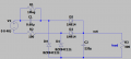
This is a transformer less power supply. It used C1 as the current/voltage limiting device.
If you put 0.68uF across the power line current flows through the cap. (high voltage cap) Keep that in your head.
This works best if the line voltage is high (120 or 240) and out output voltage is much smaller. (5 or 12)
In this schematic D4 and D1 are Zeners to limit the output voltage to about 11V. More often I use normal diodes for all four spots and put a single Zener across the load, to limit the voltage.
Most internet schematics call out 1N4007. (high voltage diodes) I use 50V diodes. We made many of these.
C1 limits the current to some value. (I don't remember say 40mA). That current flows through the full wave bridge and make current for the load. If the load is not using all the current the Zener will take the extra current.
1774886388136.png
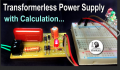
This kind of power supply is commonly used for LED night lights, smoke alarms, small computers that monitor the environment, battery chargers, etc. There is no isolation from the power line! Normally they are used in applications where a small amount of power is used. Used where a human cannot touch the PCB.
1774887341835.png
See C1 the high voltage cap in red. Four N4007 diodes, 5V Zener diode, the output cap is at the top right side.
 

MisterBill2

Joined Jan 23, 2018
28,508
The inductor you are looking at is about the same size as a transformer. Just us the transformer.
Theother advantages of using a transformer are both isolation and better regulation. The safety benefit is that if the low voltage portion becomes open circuited the output drops to zero instead of rising towards the mains voltage. THAT advantage is possibly a very "big deal", for connecting to a cell phone charge port that might not have adequate over voltage protection.
 

MisterBill2

Joined Jan 23, 2018
28,508
What I see in post #37 is an example of some of the larger and more expensive phone chargers. BUT those are only for 120 volt sources. Probably similar ones for 220 volts are available, BUT it is also possible that in some localities in some pats of the world, the local government has created rules that demand much more expensive chargers. I AM AWARE that such things have been done.
 

Orson_Cart

Joined Jan 1, 2020
110
There are standard circuits for a 2 diode, 2 SCR bridge into a choke input filter to provide regulated power - usually for >= 500W say, for very low power there are a myriad of solutions, OP should post output requirements, oh - I see 5V 1A, if you have to make your own with a transformer ( 50Hz per the thread title ) then a FWR ( 4 diodes ), 1000uF cap and a 7805 regulator on a small heatsink.
 
Last edited:
Top