Facebook
 Google
 GitHub
 Linkedin
I'm making a 5 band equalizer based on a circuit diagram I found on the Internet.
I implemented the entire circuit on a breadboard, but it didn't work.
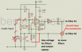
I'm going to proceed with this circuit while checking if it works properly every time I finish a part, but the buffer part (gain 2, non-inverting amplifier) doesn't seem to be working properly.
I learned that a buffer circuit is used to reduce the noise of an input audio signal, and I know that the shape of the input signal and output signal should be similar.
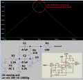
However, in the circuit implemented on the breadboard, the output signal is not output properly, and in the pspice simulation, 0V or less is cut off and displayed.
Is this circuit diagram wrong? Or am I having this problem because I haven't finished the whole circuit yet?
whole circuit diagram

buffer circuit - it's 5band( 60Hz, 250Hz, 1000Hz, 4000Hz, 16000Hz) so i put 60hz Sine wave.

pspice simulation

I implemented the entire circuit on a breadboard, but it didn't work.
I'm going to proceed with this circuit while checking if it works properly every time I finish a part, but the buffer part (gain 2, non-inverting amplifier) doesn't seem to be working properly.
I learned that a buffer circuit is used to reduce the noise of an input audio signal, and I know that the shape of the input signal and output signal should be similar.
However, in the circuit implemented on the breadboard, the output signal is not output properly, and in the pspice simulation, 0V or less is cut off and displayed.
Is this circuit diagram wrong? Or am I having this problem because I haven't finished the whole circuit yet?
whole circuit diagram
buffer circuit - it's 5band( 60Hz, 250Hz, 1000Hz, 4000Hz, 16000Hz) so i put 60hz Sine wave.
pspice simulation