Buck converter circuit wont work in LTspice

Thread Starter

Heiko Mihkelson

Joined Jul 13, 2018
5
Hi

I have been designing a charger for my robot project and I am stuck with a buck concerter design in LTSpice. For some reason I cant get a square wave output from my mosfets. If I connect the V2 voltage source directly between the V1 + terminal and mosfet's gate it works, but if I try to make a more realistic circuit, it does not pass the suare waves to mosfet's output.

If anyone could point out my mistake, it would be great!

Thanks in advance
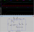
upload_2018-7-13_23-39-56.png
 

crutschow

Joined Mar 14, 2008
38,598
Look at the gate charge/capacitance in the data sheet for the two MOSFETs (why two of them?) and tell me how long it takes to transfer that charge through a 100kΩ resistor to turn the MOSFET Off.
(You do understand RC time-constants and risetime?).
 
Last edited:

Thread Starter

Heiko Mihkelson

Joined Jul 13, 2018
5
Thank you for the tip. It really was about the time constant. I lowered the driving resistors and added some caps to get a smuther output. I also added some transistors to make a 3A protection if my pwm on the MCU should fail. I attached a file aswell for other hobbyst like me.

Thank you once more!
 

Attachments

crutschow

Joined Mar 14, 2008
38,598
You didn't answer my question about why two MOSFETs?
They are only needed if you are trying to block a signal in both directions.
Here you only need to block it in one direction.
You just need one P-MOSFET with the source terminal going to the left.
 

crutschow

Joined Mar 14, 2008
38,598
In my second post i added a battery in the place of R1. Hence the charger.
Okay, I didn't notice that change.
There is two mosfets because my MCU needs to measure 0v input voltage if the input is disconnected.
If the input is disconnected, you will measure the battery voltage minus a diode drop if you use a single MOSFET.
Wouldn't that be sufficient to tell you that the input is disconnected?
 
Top