Need Protection circuit for DC-DC Buck Converter

Thread Starter

ommsiva

Joined Mar 13, 2024
52
Hi to all,

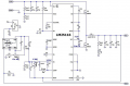
Previously I constructed building 0-30V , 0-10A regulated power supply using 24V-0-24V @10 A transformer, I failed many times by building circuit using Linear Ics and current boosting technique.

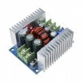
Now have purchased 300W 20A DC-DC Buck Converter Step-down Module but it does not have any protection circuit.

I have attached the module , Kindly give some ideas and circuit for protecting the module which we can anticipate while using as a lab bench power supply.

Thank you all.
 

Attachments

MisterBill2

Joined Jan 23, 2018
27,159
What do you want to protect your module from?? Overload protection is a good choice for a bench supply, Protecting from line voltage transient spikes is also a good choice, but much different. Protecting the supply output from an accidental mains voltage connection is also a good choice.
So there you have three types of protection that are each quite different and require different circuits.
I see two very small adjustable resistors, which might be to adjust the output voltage and a current limit. Those adjustments should be protected against mechanical damage, and the whole module should be protected from short circuit damage which will certainly happen if the bottom contacts conductive items on top of the bench,
 

Thread Starter

ommsiva

Joined Mar 13, 2024
52
What do you want to protect your module from?? Overload protection is a good choice for a bench supply, Protecting from line voltage transient spikes is also a good choice, but much different. Protecting the supply output from an accidental mains voltage connection is also a good choice.
So there you have three types of protection that are each quite different and require different circuits.
I see two very small adjustable resistors, which might be to adjust the output voltage and a current limit. Those adjustments should be protected against mechanical damage, and the whole module should be protected from short circuit damage which will certainly happen if the bottom contacts conductive items on top of the bench,
here is the circuit, check this and give additional protection circuits required for complete design of power supplies.
 

Attachments

DickCappels

Joined Aug 21, 2008
10,661
It is a current mode converter so it should take care of itself in the event of a load fault (short inter output). Maybe you would like (and probably should anyway) put a fuse in series with the inout.
 

Thread Starter

ommsiva

Joined Mar 13, 2024
52
It is a current mode converter so it should take care of itself in the event of a load fault (short inter output). Maybe you would like (and probably should anyway) put a fuse in series with the inout.
What type of protection should be added to the module while checking dc motor
 

DickCappels

Joined Aug 21, 2008
10,661
The inherent current limiting would probably be sufficient.

The only thing I might add is a crowbar to protect against over-voltage but that would probably not be an issue. I would defer to one of the members with more motor drive experience on this one.
 

MisterBill2

Joined Jan 23, 2018
27,159
Understand that this module IS NOT A POWER SUPPLY! It is a voltage and current REGULATOR, that requires a DC input supply. And the circuit shown also implies that a Vcc source is needed to power the internal 5 volt regulator.
As others have explained, it is internally protected against overloads because it already includes current regulation. What it IS NOT protected from is an excessive Vin supply voltage or a reverse polarity supply input.
The one protection I would add would be against the application of either polarity power source to the output while the input was not powered.
AND, since we are not given any specifications information at all, we have no hint as to what the original designer would protect against. But wrong connections should certainly be avoided.
 

Thread Starter

ommsiva

Joined Mar 13, 2024
52
Understand that this module IS NOT A POWER SUPPLY! It is a voltage and current REGULATOR, that requires a DC input supply. And the circuit shown also implies that a Vcc source is needed to power the internal 5 volt regulator.
As others have explained, it is internally protected against overloads because it already includes current regulation. What it IS NOT protected from is an excessive Vin supply voltage or a reverse polarity supply input.
The one protection I would add would be against the application of either polarity power source to the output while the input was not powered.
AND, since we are not given any specifications information at all, we have no hint as to what the original designer would protect against. But wrong connections should certainly be avoided.
Here is the datasheet.
 

Attachments

MisterBill2

Joined Jan 23, 2018
27,159
The data sheet confirms that it is a REGULATOR, and certainly that would be an important part of a power supply.
From post #1 the goal is a power supply able to deliver a voltage up to 30 volts at a current of UP TO Ten amps. These are entirely reasonable numbers. The specification states a required input supply range of 40 to 60 volts. I did not see a specification for the maximum allowable ripple voltage, so I am guessing that a simple transformer and rectifier supply with one stage of filtering may be adequate. If the transformer/rectifier/filter system is part of the same package, then the major protection will need to be against overheating. A single fan should be adequate for that. A simple thermostatic temperature switch could operate an "overtemp" warning signal.
 
Top