Facebook
 Google
 GitHub
 Linkedin
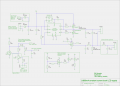
The 7.5V onboard supply - a buck regulator - provides up to 100mA of current. The driver uses about 35mA, leaving about 65mA for comparators - 7.5V should be fine, right?I don't know what you expect me to say about the above statement; it doesn't make a lot of sense.
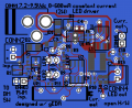
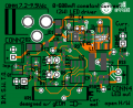
The design would be ideally flexible, but the PCB would almost certainly change for higher powered models.If you want to make this thing somewhat flexible, you might plan on using discrete MOSFETs instead of arrays, as you'll have a much wider selection.
Ah, good idea. Yes, I did read the datasheet. However, I am still a noob - a student learning electronics, so some things don't make sense to me. The datasheet says: "Operating Temperature -40 °C to +125 °C (Temperature rise included)" which would seem to indicate that running at Irms(max) would allow it to operate up to 125°C, unless I'm missing something. Although I wouldn't run it at maximum load, inductors are basically finely wound coils of wire, so the only thing that could go wrong is the wire could melt or break, right?Did you look at the specs? If you want good performance and long life, then de-rate the components by 50% or more. Irms(max) for that inductor is 3.2A, and it will saturate @4.1A. You do not want to get close to saturating it, or you will see smoke.
I'll be way clear of Isat.See Ronald Dekkers' "Flyback Converters for Dummies" page for a 'scope image of inductor saturation. Power dissipation in the upper MOSFET will skyrocket.
When I get the time to make some PCB's I'll do this.You'll have to see how it does on a test bench. Start out using resistors, and then decrease their values to see what ringing you get.
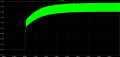
I'm not entirely sure how to do this. I only started using LTspice about 3 days ago.Why don't you test the model using LTSpice, and see if it agrees with the datasheet?
")