Buck Boost Converter for MPPT

Thread Starter

DThompson

Joined Sep 21, 2021
12
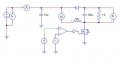
I've been designing a non-inverting buck-boost converter with a low side switch (see image) for use as an MPPT controller. In simulation, it appears to buck and boost voltage adequately, but when prototyping the circuit, there is no voltage output and the switch(N-channel MOSFET) noticeably heats up. Could this be due to inductor saturation, incorrect switching or some other factor?
 

Attachments

ronsimpson

Joined Oct 7, 2019
2,985
SPICE allows you to do things that do not work in real life.
10uH is very small. You must be running at a high switching frequency.
I have never seen this type of circuit. There are many examples of buck/boost that do work.
The MOSFET must be switching. I think you went to 100% duty cycle which will not be good.
 

Thread Starter

DThompson

Joined Sep 21, 2021
12
SPICE allows you to do things that do not work in real life.
10uH is very small. You must be running at a high switching frequency.
I have never seen this type of circuit. There are many examples of buck/boost that do work.
The MOSFET must be switching. I think you went to 100% duty cycle which will not be good.
Switching Frequency is 500kHz. I chose a low-side switch with an N-channel FET because it's easier to drive than the high-side switch in regular buck-boost circuits. Would it be better to use the regular inverting buck-boost design even though its harder to switch?
 

Papabravo

Joined Feb 24, 2006
21,157
If you simulator can show the power dissipation in the switch that would provide a clue. The generator driving the switch "suggests" that a triangle or sawtooth waveform is being used. If that is the case it means the switch is operating in the linear range and providing a "short" circuit across the switch most of the time. This would be bad "juju".
 

Thread Starter

DThompson

Joined Sep 21, 2021
12
If you simulator can show the power dissipation in the switch that would provide a clue. The generator driving the switch "suggests" that a triangle or sawtooth waveform is being used. If that is the case it means the switch is operating in the linear range and providing a "short" circuit across the switch most of the time. This would be bad "juju".
I'm simulating using PSIM, so I used a comparator with a DC and sawtooth as input to produce a square-wave into the switch. The average power dissipation in the switch during simulation, for a 150W input, is 640mW which doesn't seem to be a problem.
 

Papabravo

Joined Feb 24, 2006
21,157
I'm simulating using PSIM, so I used a comparator with a DC and sawtooth as input to produce a square-wave into the switch. The average power dissipation in the switch during simulation, for a 150W input, is 640mW which doesn't seem to be a problem.
Although it seems unlikely that 640 mW would cause a noticeable temperature rise, you can check the datasheet for a thermal resistance parameter, with units of °C/Watt. The one you want tells you the temperature rise from junction to ambient. Multiply this number by 0.64 Watts an that should be close to the temperature of the device in "open air". Of course if you have it mounted to a heat sink you will have to take that into account as well.

You may also have other problems, but we try to knock them down one at a time.
 

Thread Starter

DThompson

Joined Sep 21, 2021
12
Although it seems unlikely that 640 mW would cause a noticeable temperature rise, you can check the datasheet for a thermal resistance parameter, with units of °C/Watt. The one you want tells you the temperature rise from junction to ambient. Multiply this number by 0.64 Watts an that should be close to the temperature of the device in "open air". Of course if you have it mounted to a heat sink you will have to take that into account as well.

You may also have other problems, but we try to knock them down one at a time.
Yeah it should only rise less than 1°C and its heating up way more. I think the problem is that the Gate-Source voltage isn't high enough above the threshold to switch it on and off completely, causing heating up if that's correct?
 

Papabravo

Joined Feb 24, 2006
21,157
Yeah it should only rise less than 1°C and its heating up way more. I think the problem is that the Gate-Source voltage isn't high enough above the threshold to switch it on and off completely, causing heating up if that's correct?
If the waveform on the gate was the problem and you see heating then something is not as it has been represented. That would incompatible with a power dissipation of 0.64 watts.
 
Top