Buck-Boost converter - finding voltage and current.

Thread Starter

HappyC4mper

Joined Oct 13, 2017
71
Hey guys,
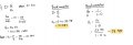
I've worked out the output voltages of the buck and boost converters. My question is, How would I calculate the voltage across the inductor when the switching transistor is ON and how would I be able to calculate the current for each of the converters assuming that there is no power loss in both converters?


Attached below is my workings so far.
Solar panel provides the MPP of 175W at current 7.42A
 

Attachments

MrAl

Joined Jun 17, 2014
11,486
For the buck, think about what the output is normally, and then what the input is normally, then note taht the inductor is right across the two. So what would the voltage across the inductor be?
 

Thread Starter

HappyC4mper

Joined Oct 13, 2017
71
For the buck, think about what the output is normally, and then what the input is normally, then note taht the inductor is right across the two. So what would the voltage across the inductor be?
to calculate the current of the conductors, which equation needs to be used? Do they both use the same equation(same question for the voltage difference)?
 

MrAl

Joined Jun 17, 2014
11,486
to calculate the current of the conductors, which equation needs to be used? Do they both use the same equation(same question for the voltage difference)?
Well the buck inductor with the switch 'on' has the input voltage on one side and the output voltage on the other side (terminal) of the inductor, while the boost has the input voltage all across the inductor when the switch is 'on' so they cant both have the same equation.

Do you know anything about averaging equations for switching regulators?
Also, do you think you could post the two schematics here so we are both talking about the same circuits?

The current through the inductor always follows:
v=L*di/dt
so:
di=v*dt/L

but you also want to calculate the average current in most cases which is sometimes very easy to do.
 
Top