Bridge Rectifier Average Voltage

Thread Starter

jegues

Joined Sep 13, 2010
733
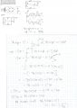
See figure attached.

Okay I can see how these circuit acts like two full wave rectifiers in one and I was also able to reproduce the plot shown.

The part I get confused about is how he simplifies the integral when he is solving the average voltage.

I didn't simplify anything and worked out the integral and got stuck because I don't have theta.

How is he preforming this simplification, he indicates that Vs>>0.7 but I don't see how that reduces to what he's got.

Can someone clarify?
 

Attachments

Thread Starter

jegues

Joined Sep 13, 2010
733
Instead of using ωt, he uses θ.

Are you confused how he found θ at the end?
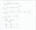
I am confused as to how he evaluated his integral, he makes an assumption and it simplifies to \(\frac{2Vs}{\pi} - 0.7\)

How does he make that simplification? How does the integral come out to be that?
 

mik3

Joined Feb 4, 2008
4,843
I am confused as to how he evaluated his integral, he makes an assumption and it simplifies to \(\frac{2Vs}{\pi} - 0.7\)

How does he make that simplification? How does the integral come out to be that?
If you assume that the integral is evaluated from 0 to π and assume that the peak value of the sine wave is Vs-0.7. However, I find that the answer is \(\frac{2Vs}{pi}-1.4\)
 

Thread Starter

jegues

Joined Sep 13, 2010
733
If you assume that the integral is evaluated from 0 to π and assume that the peak value of the sine wave is Vs-0.7. However, I find that the answer is \(\frac{2Vs}{pi}-1.4\)
So the limits on his integral are suppose to be from 0 to \(\pi\)?
 

Thread Starter

jegues

Joined Sep 13, 2010
733
If you assume that Vs is much greater than 0.7 you will get a good approximation of Vavg.
I'm trying to figure out how he went from the line with the integral to the line directly below it.

I can see that he assumed Vs >> 0.7 but that doesn't make it clear to me how that results in,

\(\frac{2V_{s}}{\pi} - 0.7 = 15\)

Can you clarify that portion of the mathematics or trickery or whatever he seems to be doing?
 

mik3

Joined Feb 4, 2008
4,843
I'm trying to figure out how he went from the line with the integral to the line directly below it.

I can see that he assumed Vs >> 0.7 but that doesn't make it clear to me how that results in,

\(\frac{2V_{s}}{\pi} - 0.7 = 15\)

Can you clarify that portion of the mathematics or trickery or whatever he seems to be doing?
Solve the integral as he does in the example but with the limits 0 and π.

I found that this is: \(\frac{2Vs}{pi}-1.4\)
 

Thread Starter

jegues

Joined Sep 13, 2010
733
Your method is right but you have to divide by π and not by 2π. If you do this you will get the right answer. My answer was wrong because of a stupid mistake!
So is his original integral incorrect? It should be a \(\frac{1}{\pi}\) on the outside of the integral?
 

Thread Starter

jegues

Joined Sep 13, 2010
733
Yes, because you integrate over half of the period.
Why only half the peroid for the average voltage?

I think you should be able to use the full peroid and still obtain the correct result.

If you use half the peroid and calculate the average voltage it should be the same as if you where to do the integral over the full period right?

I'm just trying to understand how he got the integral, the constant outside the integrand and the limits on the integrand.

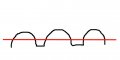
From the picture, it doesn't like as though Vo is nonzero from 0 to pi, its looks more like it is nonzero from θ to (π - θ) so why aren't we integrating with those limits?
 
Last edited:
Is the function inside the integral correct?
It seems to me that by using that function, you would include some of the negative voltage that the rectifier should have gotten rid of. For example, when theta is equal to zero, Vsin(theta) - 0.7 = 0 - 0.7 = -0.7.
Is this integral a true average of the rectified signal?
 

Adjuster

Joined Dec 26, 2010
2,148
For a more accurate result, you could determine the time limits of the period of conduction (for which Vs > 0.7), and integrate over that period. The voltage would be assumed to be zero at other times.

This probably won't make much difference, assuming that Vs max>> 0.7V. In any case, in practice the diode drop is not a perfectly constant 0.7V.
 
Top