Facebook
 Google
 GitHub
 Linkedin
ronsimpson
- Joined Oct 7, 2019
- 4,753
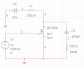
C1 is there to ac couple the pieso. No dc will be on the Pieso.It's drawn backwards and I didn't hear him explain why L1 and C1 were required
L1 is there to increase the output voltage. There can be ac voltage across a coil but no dc voltage. The average voltage across L1 is zero. So if Q1 is on for 50% of the time there is 24V and some time across L1. When Q1 is off the voltage will increase to about 50 volts for about the same time.