Boost convertor efficiency

Thread Starter

Hamza100

Joined Dec 18, 2021
12
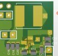
We are designing a boost convertor using MP3422 chip. The input voltage range from 2.4-4.2V and the output voltage is 5V fixed. We are facing issue of low efficiency of boost. Here are some data we have calculated:
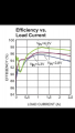
*For 0.3A output current and 2.61V input voltage, the input current is 0.71A. The efficiency is 81%
*For 0.3A output current and 4.15V input voltage, the input current is 0.41A. The efficiency is 89%.
*For 0.6A output current and 2.43V input voltage, the input current is 1.55A. The efficiency is 75%.
The expected efficiency is more than 90% from the datasheet. We have designed the same circuit as mentioned in the datasheet(https://pdf1.alldatasheet.com/datasheet-pdf/view/1036198/MPS/MP3422.html). Any suggestions on how we can improve it or the boost are only that efficient?
 

Attachments

crutschow

Joined Mar 14, 2008
34,285
Low efficiency could result from any number of issues.

How is the circuit laid out?
A plug-in type breadboard will not work well at its high operating frequency (600kHz).
For proper results it should be laid on on a PCB as show in Figure 2 on page 14 of the data sheet.

What is the exact inductor you used for L1?

For this device it would be easier to use the evaluation board they sell to get proper operation with the stated efficiencies.
 

Thread Starter

Hamza100

Joined Dec 18, 2021
12
Low efficiency could result from any number of issues.

How is the circuit laid out?
A plug-in type breadboard will not work well at its high operating frequency (600kHz).
For proper results it should be laid on on a PCB as show in Figure 2 on page 14 of the data sheet.

What is the exact inductor you used for L1?

For this device it would be easier to use the evaluation board they sell to get proper operation with the stated efficiencies.
The circuit is laid out as mentioned in figure 2 on page 14 of the datasheet. We are using PCB, not plug-in components.
The value of the inductor used 1.5uH which is the range of the inductance mentioned.
An evaluation board can be a good option however I do not have it now. The question is if these efficiencies are in a reasonable range and how should we improve it.
Sorry for the late reply.
 

DickCappels

Joined Aug 21, 2008
10,152
crutschow asked for the complete information about the inductor. The current rating is an instant indicator of whether the inductor is being mis-applied, but the DC resistance and any frequency dependent charactaristics are also of great interest.
 

ronsimpson

Joined Oct 7, 2019
2,989
From post #5. We don't know which 1.5uH inductor. Is anything hot or warm? IC? Inductor? Are you using ceramic capacitors?
The power loss is only a fraction of a watt so something should be warm, probably not hot.
1646317717436.png
 

Thread Starter

Hamza100

Joined Dec 18, 2021
12
Guys, I am thankful for your help in this thread. I have made a video using an oscilloscope for the Boost Output. It is giving a rippling voltage in the range of 4.9-5.3 with an RMS of 5.13V. I am running an Arduino with it that is measuring a Voltage. The measurement of Voltage is unstable due to this ripple, which is causing instability in the input to the Arduino. I am attaching the design of my PCB which is according to the datasheet and image of the oscilloscope.
 

Attachments

Top