Kick start shouldn’t matter, they generally only rotate the engine so the magneto sends a spark. It sounds like a short somewhere... electrical problems are the worst, it takes a lot of time to check for shorts unless it’s really obvious like burnt or bare wires. Check your relays, connectors and for oversized fuses (this is a no no).
@Wolframore Ordinarily I would agree with you, except that the one thing that's failed on both clusters is the over-voltage transient suppressor - the one thing on the board that shouldn't be affected by a harness short.
There are no outputs from the cluster to short in the harness, they are all inputs, generally a sensor or switch to ground. The problem appears to be internal to the cluster, unless it's something physical, like an over-long screw shorting a track to ground but that wouldn't explain the circumstances of the initial failure, and even if it was a short it wouldn't explain the failure of that diode. Yoshi said it was putting the battery back after charging, & reconnecting the earth lead. Clearly that caused a transient which killed board #1. The only way I can see a transient large enough to do that would be kickback from either the ignition coil or the magneto if the ignition was left switched on. That wouldn't explain board #2 failure unless the result of the previous attempt had fried the voltage regulator, in which case it's possible that the magneto open circuit AC voltage of 35+ volts could find its way to the board and fry #2 in the same way.
There is only one other possibility that might explain the failure. And that is if the battery was installed reversed - though that wouldn't have damaged the board immediately but it could have damaged the voltage regulator which subsequently led to the cluster failures.
Without examining the old VR and both boards it's hard to diagnose further.
I'm open to other explanations, but the failure mechanism, as unusual as it is, is hard to explain by a 'short'in the harness.
@Irving I agree with your assessment, I don’t mean a short to ground. An ignition wire short to power or stator short to power could cause this overvoltage. You should check the regulator.
I found another diagram for the cluster that's nearly identical apart from a 'revs' input on pin 4 that yours doesn't have (you don't have a rev counter I think, your rotating display is the speedo?) Its a lot clearer, though I'm not sure the colour codes are the same.
Just to try and further diagnose the problem here are some things you can try.
Apologies if this is a bit motherhoody and overly detailed, but best to ensure we're both talking about the same thing afterwards....
You told me it'll run with the cluster disconnected. If so disconnect the cluster, then start by measuring battery volts on DC 20V range with engine off, ignition on - from what you said before that should be around 12v. While still measuring, start the engine and run at fast idle. Volts should rise to around 13.5-14v approx. Increasing revs shouldn't go much higher than 14.5v @ 3000rpm or so. Switch multimeter to AC 20V, what reading do you get? If its a small number go down a range (you might not get anything useful on this last test, depends on your meter).
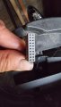
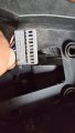
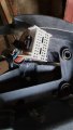
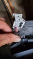
Can you post a picture of the connector that plugs onto the cluster; I've looked but couldn't find anything.
Next, does your red meter probe allow you to probe the holes on that cluster connector on the harness? Sometimes you can probe from the side or the back. If not, find a piece of wire that fits easily but snugly into the connector. A small paper-clip its usually a good fit. Wrap it tightly around your red meter probe leaving enough to push in the hole so you can easily test each circuit in turn. Now set your meter to the 20 ohm (Ω) range. Short the red probe to black probe and turn the Ω adjust control til it reads zero.
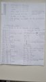
Now remove both battery fuses and connect your black probe to battery negative or a good ground point. Put your red probe on another ground point and check you get zero. If its > 0.5Ω you're probably not getting a good contact at one end or another or your ground points have corrosion under them. Now working down the connector from location 1 (Red/Green if I read it right), check the resistance at each point, some will be zero, some will be between 1 - 10Ω, and for some it will show an open circuit, in which case turn the meter up to the higher ranges to see if you get a reading (generally you won't). For some you may get a reading if you press a button or change a switch (SCROLL on pin 20 for example will be open circuit until you press the MODE button). Record your findings on a table with rows labelled 1 to 20; The pin numbering is 1 - 10 down one side of the connector, then 11 - 20 down the other.
When you've done that, put the meter on 20V DC. Reinstate the fuses. Now repeat, testing each pin for voltage. Some will be 0v, some will be 12v and some will change from 0v to 12v if you set the switches right e.g pin 1 KEY wont be 12v until you turn the ignition on, pin 2 will be 0v until KEY is on and you select RH Indicators, then it will pulse on & off.
Where you have a pin with 0v on it, try various switch combinations to see if you can force a voltage there. TBH I'll be very surprised if you did find something unexpected.
Excellent. That dual connector housing is unusual, but you can see from the various schematics that other clusters on bigger/later bikes have a dual connector. Obviously the harness is common to several bikes.
Well looking at the results, there's nothing looking fatal, but a couple of oddities. I would have expected 18 to have shown a resistance to ground for the fuel level sender but maybe its not the resistive type. And 20 should have shown 0ohm to ground if MODE was pressed on the grip. 13 is the hi-beam indicator - it should go to 12v when hi-beam is on (and ignition on probably).
There's nothing shorted to ground that I wouldn't expect to be, nor anything at 12v I wouldn't expect.
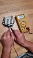
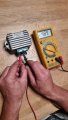
Sorry its been a while, doing a diode test on the rectifier neg on pos (of rectifier) & positive on terminal that connects to the blue wire that runs up to the speedo cluster shows 489 on the new rectifier & 508 on the old one. Could this have been the cause?
No, thats too small a difference to be an issue. You might try all pins to each other and to earth (casing) (testing each pair both ways round) and see what differences you get.
More relevant would be the voltage on the blue wire when engine is running... anything more than 22v or so would have overheated the protection diode - a poor battery earth or positive connection could have caused that, or a faulty regulator allowing the output voltage to approach that of the generator (~35v)
 Facebook
 Google
 GitHub
 Linkedin