U1 has the pinout of an LP2951.
Vin = pin 8, Vout = pin1, 0V = Pin 4. Pin 1 connects to pin 2, and pin 6 connects to pin 7 to connect up the internal feedback resistors.
Pin 3 is an open-collector "fault" indicator.
U1 has the pinout of an LP2951.
Vin = pin 8, Vout = pin1, 0V = Pin 4. Pin 1 connects to pin 2, and pin 6 connects to pin 7 to connect up the internal feedback resistors.
Pin 3 is an open-collector "fault" indicator.
I've been struggling to get a wiring diagram, I've tried to Google, 2007 sr50 carburettor version wiring diagram. A lot of them go out of focus when I zoom in.
Just to confirm, you tried a second board or a second diode?
If a second board, are the pictures of board 1 or 2? Did the chip burn on both boards?
If 2 boards have failed, the issue is outside the board. Definitely leave the 3rd one disconnected for now. Can you start it without the board connected? If not, will it start with a dead board connected? I'm wondering if your voltage regulator has failed?
Tried a 2nd board, as I read on line that these can fail due to water ingress, so I assumed that was the problem. That was the 2nd board after I asked someone to look at it, he soldered the diode back on but wasn't sure if it was the right way round. He lost the diode when I took him the 1st board to have a look at
Yes, well often the same harness is used across several models to save costs... There may be minor differences or added equipment but the basics will be similar.
I use them quite a lot (I'm not that dedicated to AAC!) I like them because they are more accurate than your average LDO, so I can get away without a separate voltage reference for my processor's A/Ds.
Your right about the protection. They do take some killing!
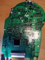
Replacement rectifier where? Do you mean the diode? Now I've seen the 1st board without the diode, I can say it was refitted on board 2 the wrong way round. The bar goes towards the other diodes... (I'll fix the cct diagram in the morning) And it's not a conventional diode, it's a transient suppressor. Which suggests the input voltage to the board was too high and it was trying to control that when it overheated and dropped off, exposing the L51a chip to a high voltage which fried it. Why board1's chip doesn't appear to be fried I don't know.
What I suggest you try is reconnecting board 1 but DO NOT try to start it. Just verify that nothing on the board is getting hot and that stuff works, eg lights, indicators, etc. Does LCD screen function OK? Then measure voltage between pin 1 (red probe) and pin 4 (black) on the 51a 8-legged chip. Should be either 3.3v or 5v.
If that "Potential" solder bridge were the cause and the solder on the diode is melting then so would the bridge. I don't think it's a solder bridge. Though it takes a good eye to spot something like that.
Problem: Diode burning up (and melting solder)
Cause: Over current.
Offending possibilities (endless) could be a shorted wire in the harness or a bad component on the board. But if it's a big enough component to cause an over-current problem then by now it should be showing signs. Unfortunately, to me the board looks in pristine condition. So either it's a component issue on the board or it's being caused by something the board is plugged into.
 Facebook
 Google
 GitHub
 Linkedin