BJT Fixed Bias Problem.

Thread Starter

cooded

Joined Jul 20, 2007
29
Hello,

I am a hobbyist and i have a problem with the bjt fixed bias circuit. Obviously i am going wrong somewhere, kindly help me rectify my problem.
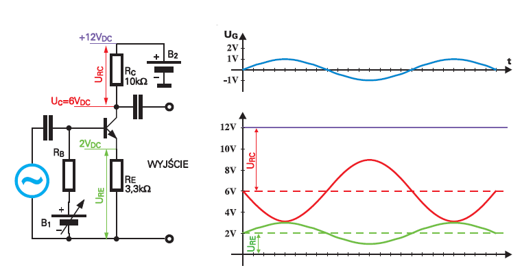
I have attached the circuit.

Here are my calculations:
When AC input = 5v then
Ib = (Vcc- 5v)/20k = 0.75mA
Considering β = 10(assumption for calculations sake)
Ic = 7.5 mA ; Ic *Rc = 7.5V and hence Vce = Vcc - (Ic*Rc) = 12.5v

When AC input = -5v then
Ib = (Vcc- 5v)/20k = 1.25mA
Considering β = 10(assumption for calculations sake)
Ic = 12.5 mA ; Ic *Rc = 12.5V and hence Vce = Vcc - (Ic*Rc) = 7.5v

So when the input voltage decreases so does the voltage across Vce and vice versa, which indicates that there is no phase shift between i/p and o/p which is not possible since we know that there exist a 180 degrees phase shift bewteen input and output. PLease do correct me with my calculations

Regards
 

Attachments

hobbyist

Joined Aug 10, 2008
892
If the beta of your transistor is around 10 -15 than you have it biased close to half supply voltage at the collector.

If you are using a real transistor the beta can be much larger and it varies considerably from unit to unit, as well as the beta is temperature and current dependant, which means that the beta is very unstable to use in designing a transistor amplifier, so other means are used to compensate for these changing parameters.

Also as was mentioned, to couple an AC signal, you need either a transformer, or a coupling capacitor.

The DC bias value of the AC source, will have influence on the base voltage of your transistor, without a coupling method described.

Also be careful with how large of a input signal you use, depending on the supply voltage as well as the transistor parameters, you can only use a amplitude that will meet the stage requiremens.
 

Audioguru

Joined Dec 20, 2007
11,248
You NEVER EVER bias a transistor like that!
You don't know the value of its current gain. It might be 10 or it might be 800. If the current gain or temperature is high then your transistor will be saturated and WILL NOT WORK!

A voltage divider with a current that is about 10 times the base current normally biases the base and an emitter resistor is normally used to reduce the effect of temperature and that every transistor has a different Vbe voltage. Sometimes a transistor base is biased with a resistor from its collector so it has negative feedback to reduce the effect listed above.
 

Adjuster

Joined Dec 26, 2010
2,148
The signal amplitude you are suggesting is really too big to be reasonable. You can't apply +5V to an ordinary silicon NPN transistor base-emitter without frying it. Even with a coupling capacitor fitted, the base would be swung between hard on, about 700mV positive, and something over 9V reverse bias. This is too much for most transistors and would most likely cause failure.

Calculating the current in the base bias resistor as you have done does not give a valid value for the base current during signal swings. The base current will of course increase as the signal goes positive, due to current coming from the signal source. This will more than offset the reduction of the voltage across the bias resistor.

Similarly, during negative signal swings the base current reduces - with these big amplitudes down to cutoff as has already been mentioned. The current flowing in the bias resistor will be diverted to the signal source.
 

Thread Starter

cooded

Joined Jul 20, 2007
29
Hello All,

Thanks for your replies. I am a newbie and i am trying to understand the working. I have attached the modified ckt diagram with a coupling capacitor. The problem described is purely a theoretical one and i know it is not practically implementable and thats why i have not considered the 0.7v drop across Vbe to switch the transistor ON. My objective is to find out the reason behind the o/p (Vce) being inverted with respect to input (Vbe). I hope my calculations are right.

Lets take the input AC signal range from 0 to 5 v instead of -5 to +5v(again i/p voltage is too high )
When I/p = greater than 0.7 v the transistor will be on. .
Let V i/p = 0.7v

Then Voltage across Rb = Vcc - Vb = 20 -0.7 = 19.3v
Ib(current into base) = 19.3/20k = 0.965 mA
If β = 10(for ease of calculations) then
Ic(collector current ) = 10*0.965 = 9.65 mA
IC*Rc = 9.65mA * 1k = 9.65v
Hence Vce = Vcc - (Ic*Rc) = 20 - 9.65 = 10.35v

Similarly,
When AC input = 5v then
Ib = (Vcc- 5v)/20k = 0.75mA
Considering β = 10(assumption for calculations sake)
Ic = 7.5 mA ; Ic *Rc = 7.5V and hence Vce = Vcc - (Ic*Rc) = 12.5v

Hence when AC i/p is equal to 0.7v the o/p is 10.35v and when AC i/p signal is 5v then Vce = 12.5v. So the o/p voltage increases as i/p voltage increases which does not mean that there is a 180 degree phase shift.

Please help me.
 

Attachments

Jony130

Joined Feb 17, 2009
5,488
Your calculations are wrong.
Read Adjuster post once more.
Calculating the current in the base bias resistor as you have done does not give a valid value for the base current during signal swings. The base current will of course increase as the signal goes positive, due to current coming from the signal source. This will more than offset the reduction of the voltage across the bias resistor.
Try to analysis this example


Vcc = 12V; Vc = 6V (red plot ); Ve = 2V (green plot) ; Vinput = 1V (blue plot).
 

Thread Starter

cooded

Joined Jul 20, 2007
29
Your calculations are wrong.
Read Adjuster post once more.

Try to analysis this example


Vcc = 12V; Vc = 6V (red plot ); Ve = 2V (green plot) ; Vinput = 1V (blue plot).

Thanks...This is my understanding now. The base current is provided by the addition of current through Rb and and the current generated by the input signal. As input signal voltage increases the current through Rb decreases and current Ic increases by a factor which β*Ib. This increase in Ic decreases the collector to emitter voltage.

Thank you all.

Regards
 

Jony130

Joined Feb 17, 2009
5,488
Lets try analysis this circuit.
The beta of the BJT is equal β=100 and the input signal is 2Vpp.
When Vin is equal 0V we have
Ic = 6mA; Ib = 60μA and voltage on the collector is equal Vc = 6V
When Vin = +1V we have
3.7V on the base of the BJT, so the emitter current is equal
Ie = 3V/330Ω = 9mA the collector current is also equal 9mA
Ic = 9mA
And collector voltage is equal
Vc = Vcc - Ic* Rc = 12V - 9V = 3V
The base current needed to provide 9mA collector current is equal.
Ib = 9mA / 100 = 90μA
The base current provider form Rb and Eb is equal
I = (Eb - Vb)/Rb = (4.7V - 3.7V) / 33KΩ = 30uA
But the emitter current must be equal to 9mA, and that's requires the base current to be equal 90uA
So we have a situation:
Eb delivers 30uA, base needed 90uA, so that extra current (60uA) will (must) be "deliver" by AC voltage source Vin.
So Vin will be deliver ( sourcing) 60uA of a current.

For the negative Vin swing (-1V)
We have this situation
Vb = 1.7V ; Ic = 3mA; Vc = 9V
The base current needed to ensure Ic=3mA is equal
Ib = 3mA/100 = 30uA
The Eb delivers I_Rb = (4.7 - 1.7V)/33K = 90uA
But we only need 30uA the base current to "deliver" 3mA of a emitter current. But Eb delivers 90uA so that extra current (60uA) must flow to Vin (must be sink by Vin).

I hope that this will help.
 

Attachments

Last edited:
Top