
BJT Driving a Reed realy_Circuit Review

Thread Starter

hoyyoth

Joined Mar 21, 2020
530
Dear Team,

I using a reed relay in my circuit. its P/N is 9011-05-11. This is the datasheet(https://www.cotorelay.com/wp-content/uploads/2014/09/9011_series_reed_relay_datasheet.pdf). Its important properties are given below.
Coil Voltage5VDC
Coil Current10 mA
Must Operate Voltage3.75 VDC
Coil Resistance500 Ohms

The BJT P/N is MMSS8050-H-TP .Datasheet is (https://www.mccsemi.com/pdf/Products/MMSS8050(SOT-23).pdf).

My circuit diagram is given below. May I know is this fine or not.

1640242477209.png
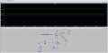
Below is my LTSpice simulation results.In simulation it is working fine.
1640242569378.png

Regards
HARI
 

Ian0

Joined Aug 7, 2020
13,227
It's good enough.
For a complete simulation you need to include the coil inductance. Then it will be obvious why the diode is needed across the coil. Not many relay manufacturers specify the inductance.
 

Thread Starter

hoyyoth

Joined Mar 21, 2020
530
It's good enough.
For a complete simulation you need to include the coil inductance. Then it will be obvious why the diode is needed across the coil. Not many relay manufacturers specify the inductance.
Hi Ian,

Thank you...
May I know is there any way to get the coil inductance data.
I think the diode is present inside this relay itself.

Regards
HARI
 

Ian0

Joined Aug 7, 2020
13,227
May I know is there any way to get the coil inductance data.
only by measuring it or guessing! Put 1H in the simulation if you don't know. Any value with show you the effect of the inductance, even if the length of time the effect lasts may be wrong. Better to have the wrong inductance than no inductance at all.

Make sure you check that it really does have a diode. If it doesn't and you think it does, it will blow up your transistor with over-voltage. If it does and you think it doesn't and you get it the wrong way round, then it will blow up your transistor with over-current, or maybe even blow up the diode in the relay.

The datasheet says "Optional coil suppression diode protects coil drive circuits", so some version do and some don't. As it is not shown on the circuit and the coil pins are not labelled + and - , then it's a fair bet it doesn't.
 

Thread Starter

hoyyoth

Joined Mar 21, 2020
530
only by measuring it or guessing! Put 1H in the simulation if you don't know. Any value with show you the effect of the inductance, even if the length of time the effect lasts may be wrong. Better to have the wrong inductance than no inductance at all.

Make sure you check that it really does have a diode. If it doesn't and you think it does, it will blow up your transistor with over-voltage. If it does and you think it doesn't and you get it the wrong way round, then it will blow up your transistor with over-current, or maybe even blow up the diode in the relay.

The datasheet says "Optional coil suppression diode protects coil drive circuits", so some version do and some don't. As it is not shown on the circuit and the coil pins are not labelled + and - , then it's a fair bet it doesn't.
Thank you Ian...
I will consider the things which you told
 

sghioto

Joined Dec 31, 2017
8,737
The circuit will work fine as drawn though the transistor and diode are overkill. You can also increase the value of R36 to 4.7K. The base current of Q6 only needs to be 1/10 of the relay current.
 

Thread Starter

hoyyoth

Joined Mar 21, 2020
530
The circuit will work fine as drawn though the transistor and diode are overkill. You can also increase the value of R36 to 4.7K. The base current of Q6 only needs to be 1/10 of the relay current.
Hi Sghhito,

Thank you. I will change the resistor.
May I know what you mean by " though the transistor and diode are overkill "

Regards
HARI
 

Thread Starter

hoyyoth

Joined Mar 21, 2020
530
A 1.5A transistor for a 10mA relay coil. Don't bother to unsolder it, but next time a BC847 (rated at 100mA) would be more than adequate.
But everybody uses a 1A diode for relay coils, because everybody has a box full of 1A diodes. A 1N4148 would also do the job.
Thank you...got it..
 

Ian0

Joined Aug 7, 2020
13,227
Why are You using a Reed-Switch when You could be using a Solid-State-Relay (SSR), ?
I don't think he's said where it goes next. From the first simulation it just looks like it is driving a logic input. Maybe all that is required is an opto-isolator (or maybe there's a good reason to use a reed relay - such as switching audio)
 

Thread Starter

hoyyoth

Joined Mar 21, 2020
530
As per my understanding, Solid-state relays are made of semiconductor devices so it will have some parasitic capacitance. Please correct me if I am wrong.
In my circuit parasitic is a concern for us.
 

LowQCab

Joined Nov 6, 2012
5,101
That FET Capacitance can be rendered close to zero.
But first you've got to stop keeping us in the dark about what you're trying to accomplish as an end result.
Do You have a proper schematic You could post ?
.
.
.
 

Thread Starter

hoyyoth

Joined Mar 21, 2020
530
The complete Schematic is not ready. This circuit is a part of our ASIC evaluation board. The Board can accommodate 5 ASIC's its different parameters are measured in a TDM fashion.
 
Top




